Eureka AIR delivers breakthrough ideas for toughest innovation challenges, trusted by R&D personnel around the world.

Separator, and fuel cell stack comprising the same

a fuel cell and separator technology, applied in the direction of fuel cell details, water management in fuel cells, electrochemical generators, etc., can solve the problems of affecting the movement and discharge of reaction gas, and no separator which can satisfy both the objects of efficiently discharging water, so as to reduce the drying of the electrolyte membrane, reduce the amount of gas flow, and reduce the effect of gas flow

Active Publication Date: 2021-03-09
LG CHEM LTD
View PDF17 Cites 0 Cited by
  • Summary
  • Abstract
  • Description
  • Claims
  • Application Information

AI Technical Summary

Benefits of technology

[0025]As described above, the separator related to one embodiment of the present invention and the fuel cell stack comprising the same have the following effects.
[0026]It is possible to efficiently distribute the gas flow and the liquid (for example, generated water) flow in the separator, and in particular, to prevent the generated water (condensed water) from flooding in the channel of the separator.
[0027]The generated water generated in the reaction gas flow path can be reused for the electrolyte membrane humidification without interfering with the flow of the reaction gas, and the water management efficiency can be improved and the drying of the electrolyte membrane can be minimized, under a low humidification or no humidification condition.

Problems solved by technology

On the other hand, the polymer electrolyte membrane fuel cell (PEMFC) requires continuous supply of moisture to maintain an ionic conductivity performance of the electrolyte polymer membrane, but the water generated in an excess flow rate and stagnated in a reaction gas flow path causes a problem that hinders movement and discharge of the reaction gas, (for example, flooding).
Also, in order to improve a water discharge performance, separators of various shapes have been developed, but there is no separator which can satisfy both the objects of efficiently discharging water and securing moisture for humidification of the electrolyte membrane simultaneously.

Method used


Image

  • Separator, and fuel cell stack comprising the same
  • Separator, and fuel cell stack comprising the same
  • Separator, and fuel cell stack comprising the same

Examples


Embodiment Construction

[0036]Hereinafter, a separator according to one embodiment of the present invention, a method for manufacturing the same, and a fuel cell stack comprising the same will be described in detail with reference to the accompanying drawings.

[0037]In addition, the same or similar reference numerals are given to the same or corresponding components regardless of reference numerals, of which redundant explanations will be omitted, and for convenience of explanation, the size and shape of each constituent member as shown may be exaggerated or reduced.

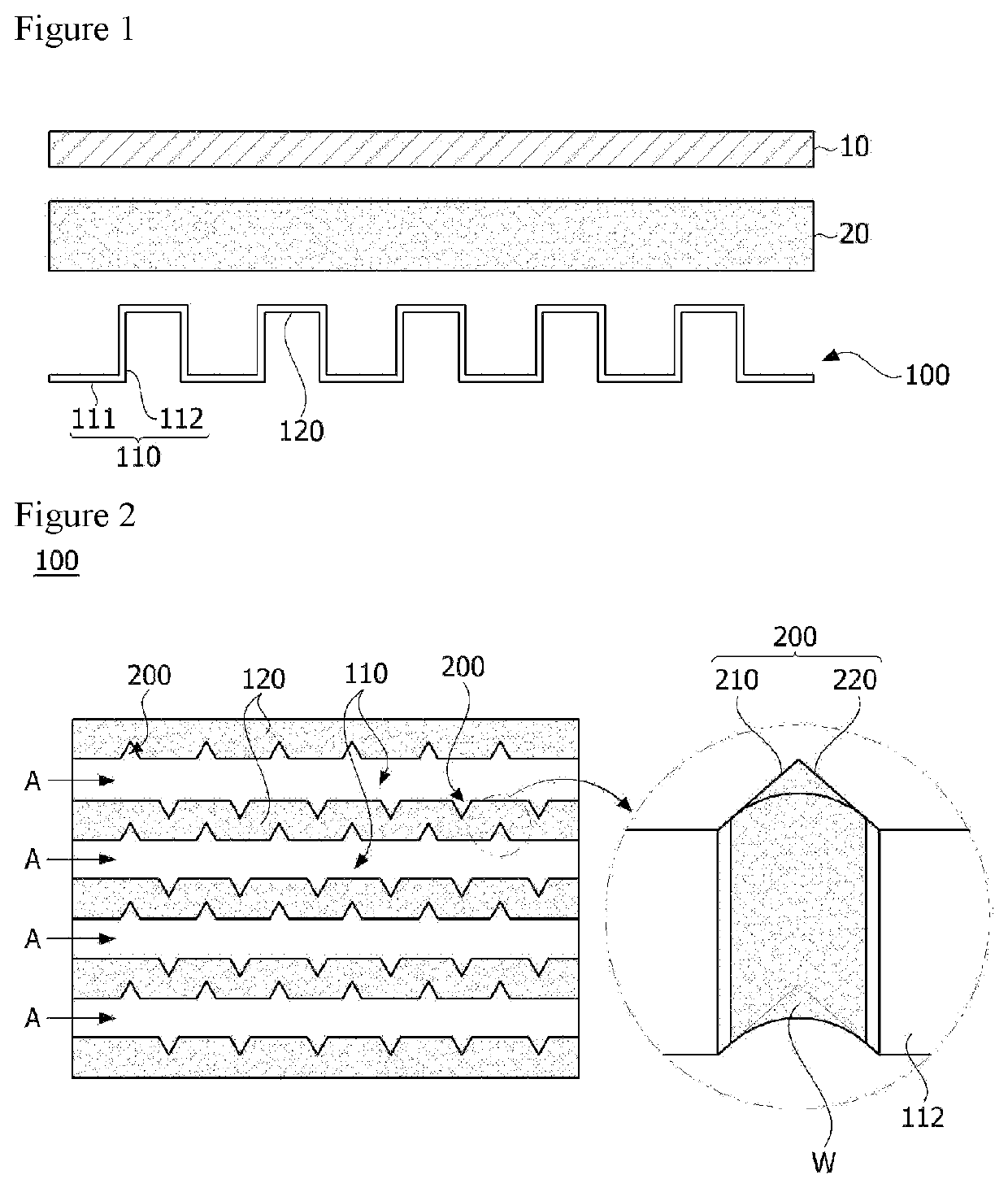
[0038]FIG. 1 is a schematic diagram of a fuel cell stack (1) related to one embodiment of the present invention, and

[0039]FIG. 2 is a plan view of a separator (100) related to one embodiment of the present invention.

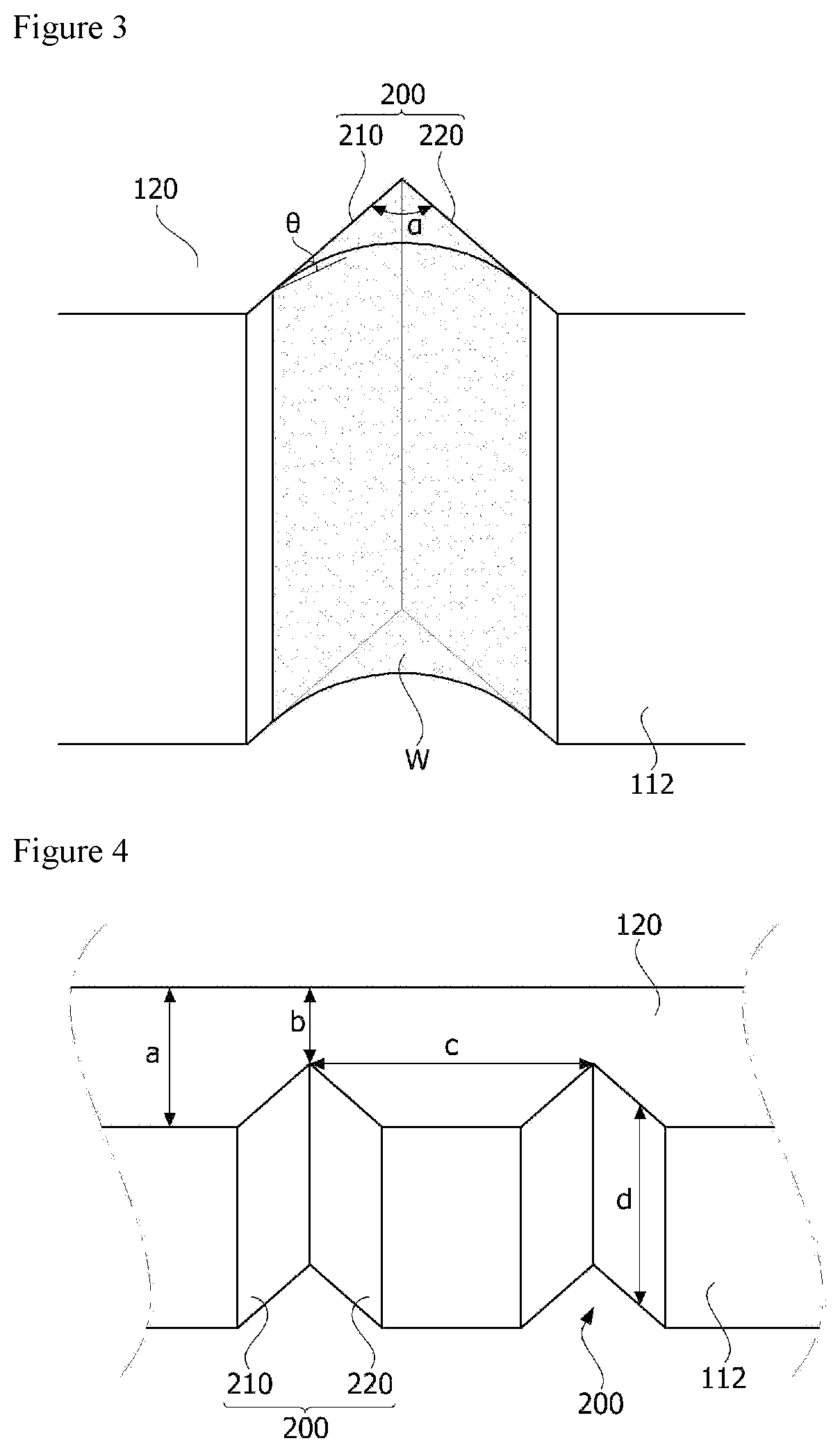
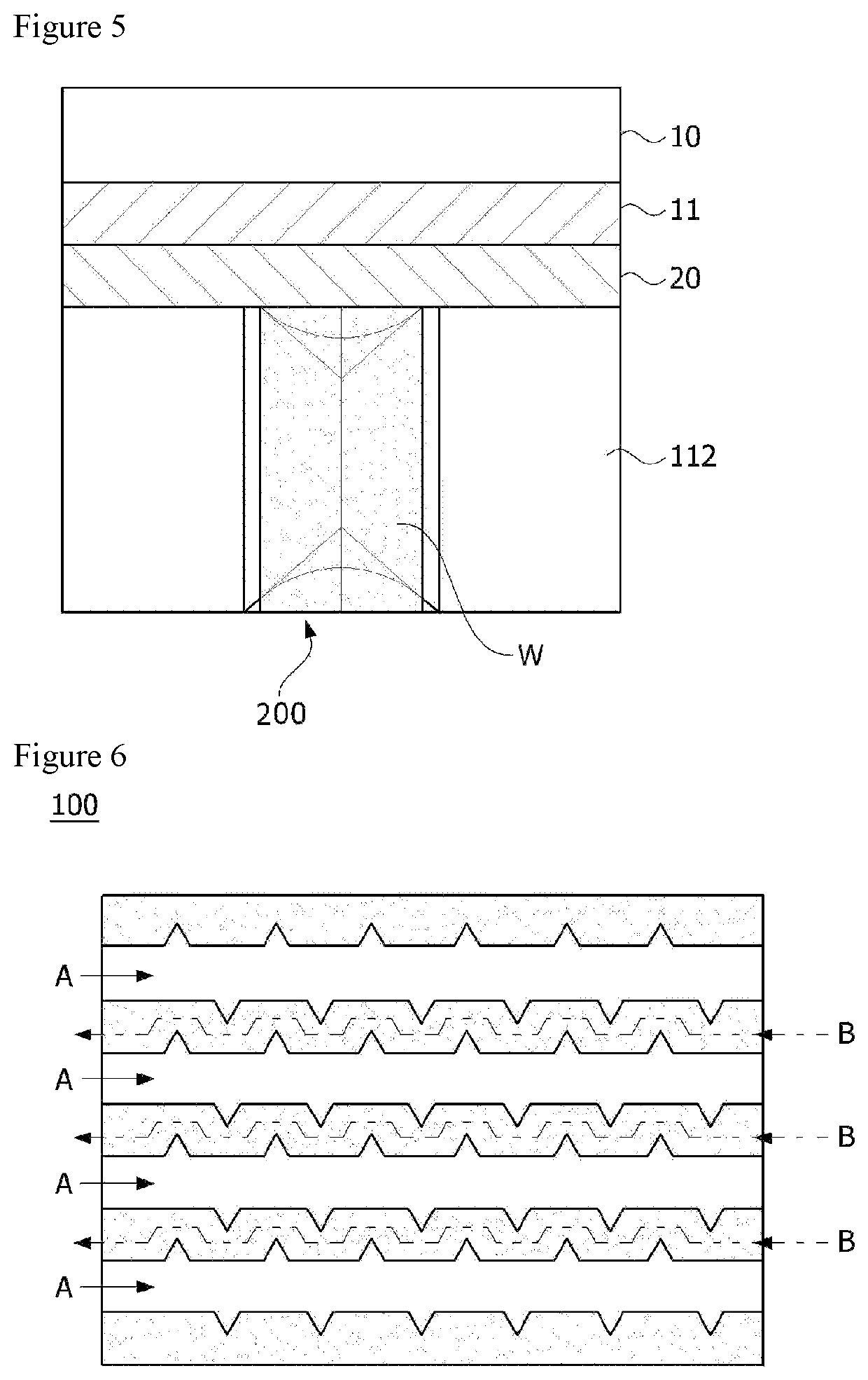
[0040]FIGS. 3 and 4 are perspective views of the water storage part (200) shown in FIG. 2, and FIG. 5 is a conceptual diagram for explaining one operating state of a fuel cell stack (1).

[0041]FIG. 6 is a plan view for explaining a re...


PUM

PropertyMeasurementUnit
contact angleaaaaaaaaaa
operating temperatureaaaaaaaaaa
angleaaaaaaaaaa

Abstract

The present invention relates to a separator and a fuel cell stack comprising the same, and according to one aspect of the present invention, there is provided a separator comprising a plurality of channels including a bottom forming a flow space for a reaction gas to flow and a pair of sidewalls connected to the bottom, and a plurality of ribs provided so as to connect the sidewalls of two adjacent channels, wherein the sidewall of the channel is provided with a water storage part which is recessed inward and has a first inclined surface and a second inclined surface connected by a first angle.

Description

CROSS REFERENCE TO RELATED APPLICATIONS[0001]This application is a 35 U.S.C. § 371 national stage application of PCT International Application No. PCT / KR2017 / 013865, filed Nov. 30, 2017, which claims priority from Korean Patent Application No. 10-2016-0163608, filed Dec. 2, 2016, the contents of which are incorporated herein in their entireties by reference. The above-referenced PCT International Application was published in the Korean language as International Publication No. WO 2018 / 101754 A1 on Jun. 7, 2018.TECHNICAL FIELD[0002]The present invention relates to a separator and a fuel cell stack comprising the same.BACKGROUND ART[0003]Generally, a fuel cell is an energy conversion device that generates electrical energy through an electrochemical reaction between a fuel and an oxidizer and has an advantage that power can be consistently generated as long as the fuel is continuously supplied.[0004]A polymer electrolyte membrane fuel cell (PEMFC) using a polymer membrane capable of p...

Claims


Application Information

Patent Timeline
Patent Type & Authority Patents(United States)
IPC IPC(8): H01M8/00H01M8/026H01M8/04291H01M8/04492H01M8/1004H01M8/1018
CPCH01M8/026H01M8/04291H01M8/04529H01M8/1004H01M8/1018H01M2008/1095H01M8/0254H01M8/0267Y02E60/50H01M8/04156
Inventor KONG, CHANG SUNJUNG, HYE MIYANG, JAE CHOON
Owner LG CHEM LTD
Why Eureka
Eureka Blog
Learn More