Roadway luminaire and methods of use

a technology for roadways and luminaires, applied in the direction of roads, traffic signals, lighting and heating apparatus, etc., can solve the problems of frequent (at least annually) luminaire failures, uneven lighting of the traffic surface, waste of uncontrolled light, etc., and achieve the effect of efficiently dispersing light and efficiently dispersing ligh

Active Publication Date: 2009-04-23
LSI INDS
View PDF39 Cites 67 Cited by
  • Summary
  • Abstract
  • Description
  • Claims
  • Application Information

AI Technical Summary

Benefits of technology

[0008]The present disclosure relates to a lighting apparatus configured to efficiently distribute light, and in particular, efficiently distribute light for illuminating roadway surfaces and, more particularly the illumination of roadway surfaces with one or more lighting sources such as LEDs in an exemplary embodiment.

Problems solved by technology

Highway and roadway lighting have used incandescent and more recently high intensity discharge (HID) luminaire s that can provide adequate amounts of lighting, but which have several drawbacks, including frequent (at least annually) luminaire failures and uneven lighting of the traffic surface.
Uncontrolled light can be wasted in lighting areas around the roadway that do not require lighting, and contributes to unwanted “night lighting” which can interfere with the preservation and protection of the nighttime environment and our heritage of dark skies at night.
As advances in the quality and energy efficiency of lighting sources such as LEDs have improved, their production costs have gone down.
The light directed into the horizon is wasted light resulting in wasted energy costs to power the LEDs.
Tilting the luminaire is thus an inefficient manner of obtaining a proper light distribution.

Method used


Image

  • Roadway luminaire and methods of use
  • Roadway luminaire and methods of use
  • Roadway luminaire and methods of use

Examples


Embodiment Construction

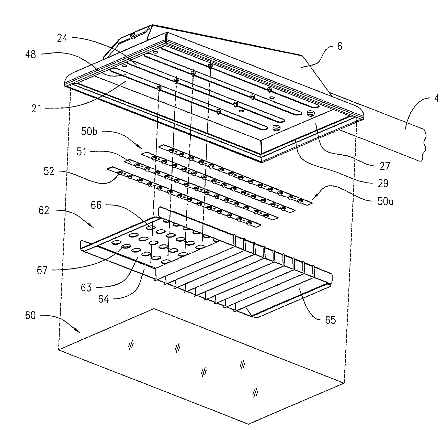
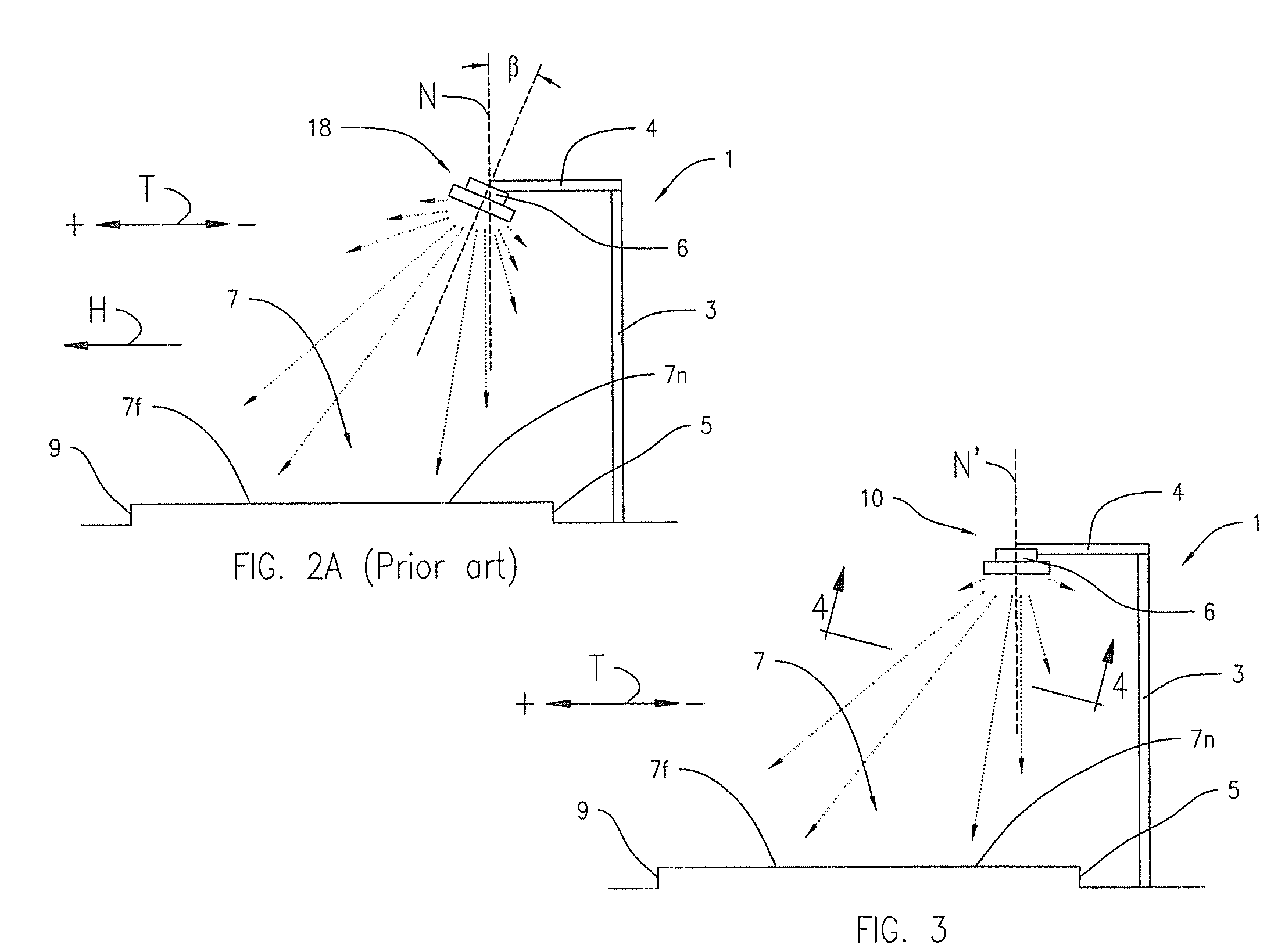
[0039]FIG. 3 shows an embodiment of the lighting apparatus 10 of the present disclosure comprising a roadway light pole assembly 1 that includes a pole 3, an arm 4 and pole adapter 6. The pole 3 is positioned away from the near edge 5 of the roadway 7, having a near lane 7n and a far lane 7f. FIG. 5 shows an exploded view of the lighting apparatus of FIG. 4. FIG. 6 shows a transverse sectional view of the apparatus of FIG. 4, including a housing 20 having a rectangular planar base 21 and a plurality of light source assemblies 50. In the depicted embodiment, the light sources are comprised of LEDs. The lighting apparatus 10 of the present disclosure can, however, employ any type of light source known to date or hereinafter created. Although, the remainder of the specification describes various embodiments of the disclosure employing LEDs as the light sources, the LEDs can be replaced with any light source known to date or hereinafter created. In the embodiment depicted in FIG. 4, the...


PUM


Abstract

A lighting apparatus having a base member and a directional member are shown and described. The base member includes a first surface having a plurality of reflective elements extending therefrom. The base member also including a plurality of openings arranged in a pattern. Each openings is configured to receive a respective light source. The directional member has a portion of a reflective surface positioned relative to at least one opening to reflect light radiating from a lighting source disposed within the opening towards a portion of at least one of the reflective elements extending from the base member.

Description

FIELD OF THE INVENTION[0001]The present disclosure relates generally to a luminaire and, more particularly, to a luminaire for lighting a roadway or the like and, even more particularly, to a luminaire directing light from its one or more light sources in more than one direction. The disclosure finds particularly useful application when the luminaire employs multiple light sources including, in one embodiment, one or more light emitting diodes (LEDs).BACKGROUND OF THE INVENTION[0002]Highway and roadway lighting have used incandescent and more recently high intensity discharge (HID) luminaire s that can provide adequate amounts of lighting, but which have several drawbacks, including frequent (at least annually) luminaire failures and uneven lighting of the traffic surface. Such lighting also disperses the light in all directions around the luminaire. Uncontrolled light can be wasted in lighting areas around the roadway that do not require lighting, and contributes to unwanted “night...

Claims


Application Information

Patent Timeline
Patent Type & Authority Applications(United States)
IPC IPC(8): E01F9/00F21V7/00
CPCF21V7/04F21V11/02F21W2131/10F21W2131/103F21Y2101/02Y02B20/72F21V7/0083F21S8/086F21V7/18F21V7/22F21V13/04F21Y2105/001F21Y2115/10F21Y2105/16F21V7/24
Inventor BOYER, JOHN D.VANDEN EYNDEN, JAMES G.
Owner LSI INDS
Why Eureka
Try Eureka