

Wide-angle imaging lens assembly
a wide-angle imaging and lens assembly technology, applied in the field of compact wide-angle imaging lens assembly, can solve the problems of ineffective berration correction of optical system, achieve favorable enlarged field of view of optical system, reduce sensitivity of optical system, and improve image quality
- Summary
- Abstract
- Description
- Claims
- Application Information
AI Technical Summary
Benefits of technology
Problems solved by technology
Method used
Image

Examples
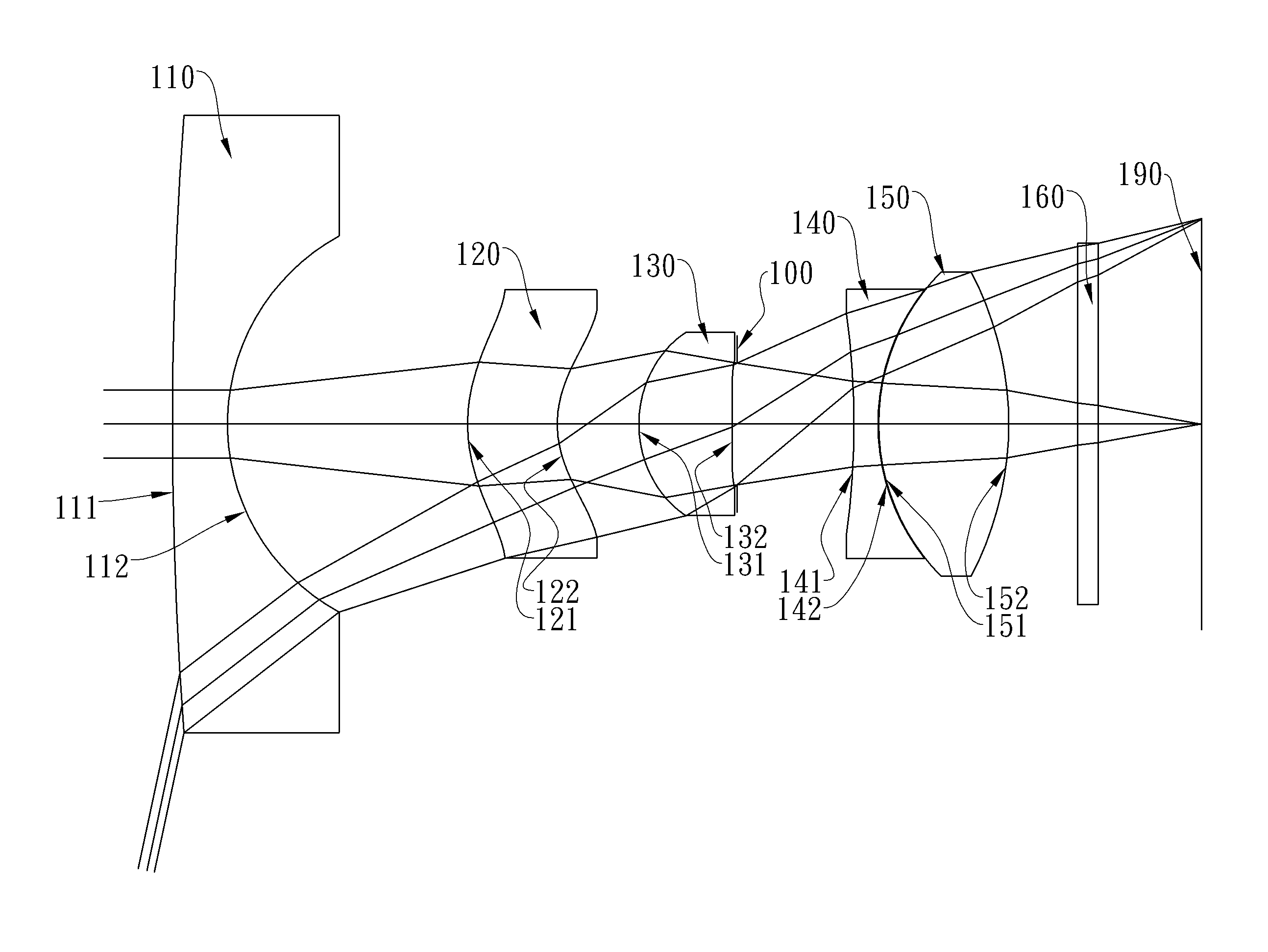
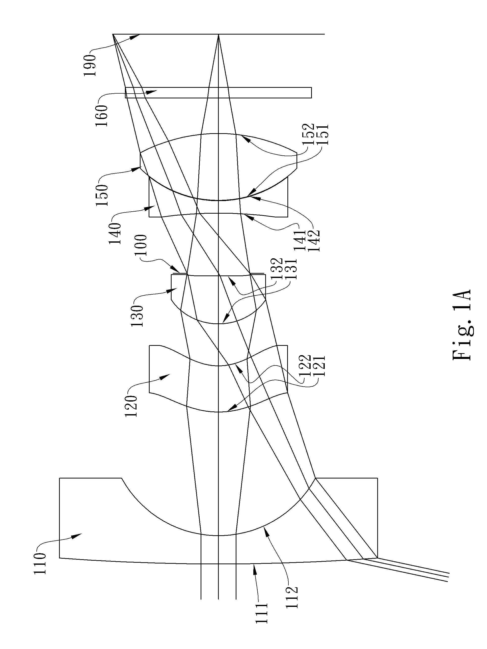
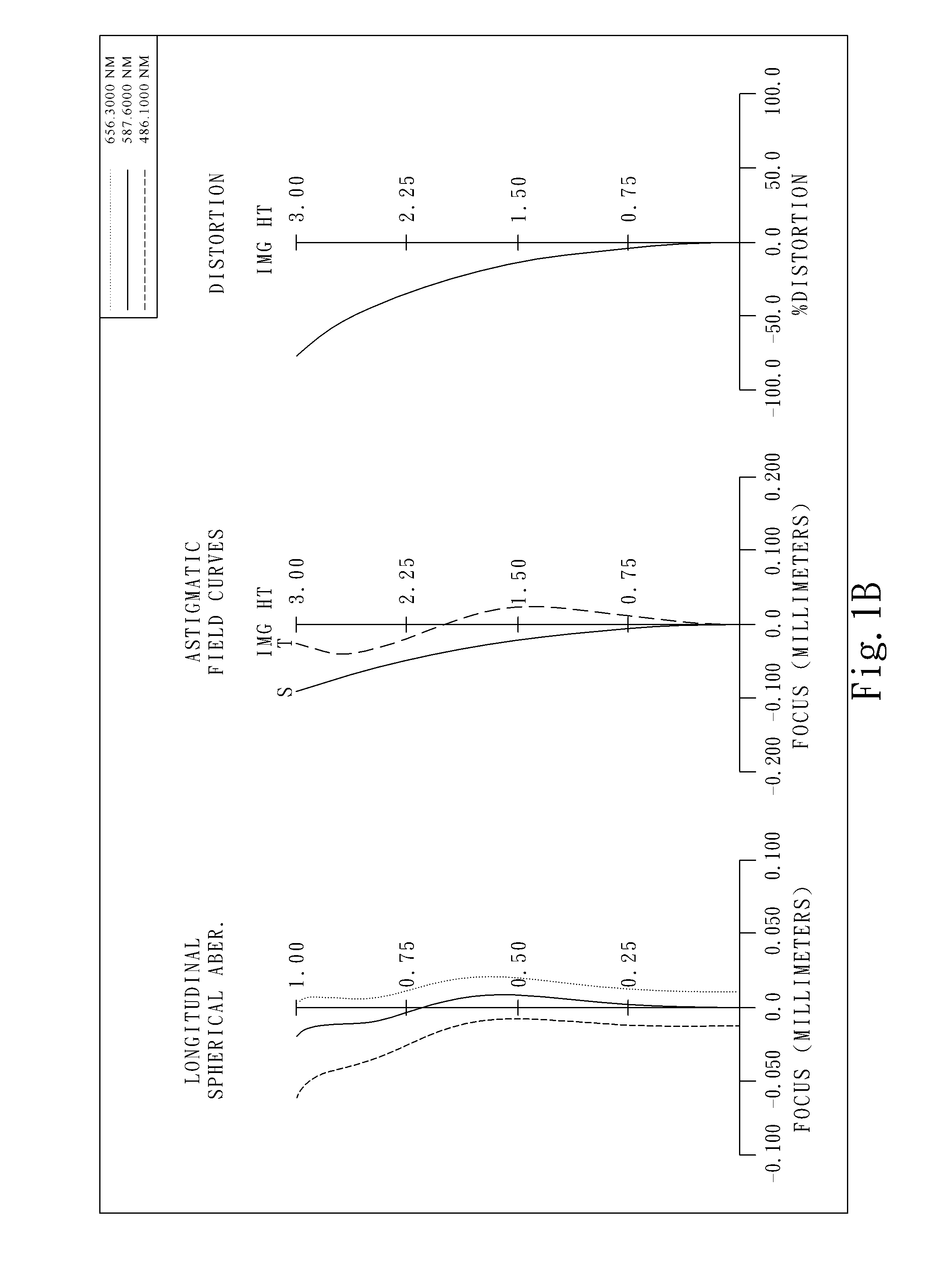
first embodiment
[0088]In the present wide-angle imaging lens assembly, the focal length of the wide-angle imaging lens assembly is f, and it satisfies the relation: f=2.78 (mm).
[0089]In the first embodiment of the present wide-angle imaging lens assembly, the f-number of the wide-angle imaging lens assembly is Fno, and it satisfies the relation: Fno=2.80.
[0090]In the first embodiment of the present wide-angle imaging lens assembly, half of the maximal field of view of the wide-angle imaging lens assembly is HFOV, and it satisfies the relation: HFOV=78.0 deg.
[0091]In the first embodiment of the present wide-angle imaging lens assembly, the Abbe number of the first lens element 110 is V1, the Abbe number of the second lens element 120 is V2, and they satisfy the relation: V1−V2=33.3.
[0092]In the first embodiment of the present wide-angle imaging lens assembly, the focal length of the first lens element 110 is f1, the focal length of the second lens element 120 is f2, and they satisfy the relation: f1...
second embodiment
[0101]In the present wide-angle imaging lens assembly, the focal length of the wide-angle imaging lens assembly is f, and it satisfies the relation: f=1.19 (mm).
[0102]In the second embodiment of the present wide-angle imaging lens assembly, the f-number of the wide-angle imaging lens assembly is Fno, and it satisfies the relation: Fno=2.20.
[0103]In the second embodiment of the present wide-angle imaging lens assembly, half of the maximal field of view of the wide-angle imaging lens assembly is HFOV, and it satisfies the relation: HFOV=84.1 deg. In the second embodiment of the present wide-angle imaging lens assembly, the Abbe number of the first lens element 210 is V1, the Abbe number of the second lens element 220 is V2, and they satisfy the relation: V1−V2=31.3.
[0104]In the second embodiment of the present wide-angle imaging lens assembly, the focal length of the first lens element 210 is f1, the focal length of the second lens element 220 is f2, and they satisfy the relation: f1 / ...
third embodiment
[0114]In the present wide-angle imaging lens assembly, the focal length of the wide-angle imaging lens assembly is f, and it satisfies the relation: f=2.68 (mm).
[0115]In the third embodiment of the present wide-angle imaging lens assembly, the f-number of the wide-angle imaging lens assembly is Fno, and it satisfies the relation: Fno=2.8.
[0116]In the third embodiment of the present wide-angle imaging lens assembly, half of the maximal field of view of the wide-angle imaging lens assembly is HFOV, and it satisfies the relation: HFOV=75.5 deg.
[0117]In the third embodiment of the present wide-angle imaging lens assembly, the Abbe number of the first lens element 310 is V1, the Abbe number of the second lens element 320 is V2, and they satisfy the relation: V1−V2=36.5.
[0118]In the third embodiment of the present wide-angle imaging lens assembly, the focal length of the first lens element 310 is f1, the focal length of the second lens element 320 is f2, and they satisfy the relation: f1 / ...
PUM
 Abstract
Description
Claims
Application Information