Check patentability & draft patents in minutes with Patsnap Eureka AI!

Shutter unit and imaging apparatus

a technology of a shutter unit and an imaging apparatus, which is applied in the direction of shutters, color television details, television systems, etc., can solve the problems of difficulty in making a and achieve the effect of higher continuous imaging frame ra

Active Publication Date: 2020-06-25
CANON KK
View PDF0 Cites 4 Cited by
  • Summary
  • Abstract
  • Description
  • Claims
  • Application Information

AI Technical Summary

Benefits of technology

The present invention is a shutter apparatus that allows for faster continuous imaging with higher frame rates. It includes a blade drive member divided into two units, and an imaging apparatus with the same. This results in higher image quality while the image is being displayed on the apparatus.

Problems solved by technology

However, in the focal plane shutter disclosed in JP 2011-113060, a bounce caused by a return movement to an exposure start position of the blade drive member is not considered after a lock by a locking member is released.
Although it is conceivable to return the blade drive member to an exposure operation start position by a charge operation after the live-view is finished, it is difficult to make higher the continuous imaging frame rate since this operation needs a time longer than that required for the return movement.

Method used


Image

  • Shutter unit and imaging apparatus
  • Shutter unit and imaging apparatus
  • Shutter unit and imaging apparatus

Examples


Embodiment Construction

[0034]Referring now to the accompanying drawings, a description will be given of embodiments according to the present invention. Corresponding elements in respective figures will be designated by the same reference numerals, and a description thereof will be omitted.

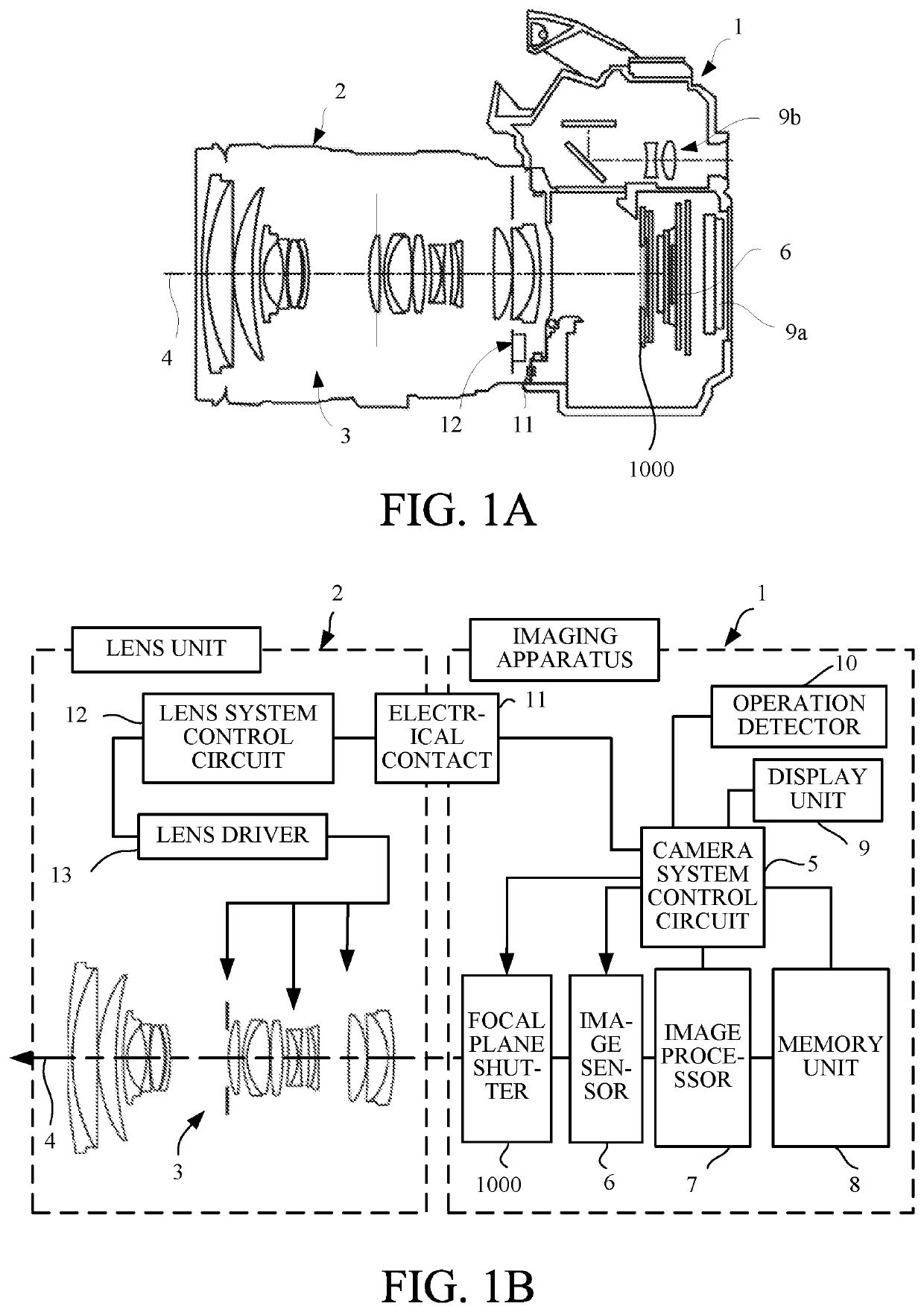
[0035]FIGS. 1A and 1B illustrate a configuration of a lens interchangeable type imaging apparatus (camera system) that is an illustrative imaging apparatus according to an embodiment of the present invention. FIG. 1A is a central sectional view of the lens interchangeable type imaging apparatus. FIG. 1B is a block diagram illustrating an electrical configuration of the lens interchangeable type imaging apparatus.

[0036]The lens interchangeable type imaging apparatus 1 includes an imaging apparatus and a lens unit 2 attachable to an imaging apparatus 1. The imaging apparatus 1 and the lens unit 2 are electrically connected via an electrical contact 11 and communicate with each other. Still images and motion images can be t...


PUM


Abstract

A shutter unit includes a base plate with an aperture, a blade member, a first drive member, a second drive member, and a charge member configured to move the second drive member from a movement completion position to a movement start position against a biasing force on the second drive member, wherein while an image obtained from an image sensor is being displayed in an imaging apparatus during continuous imaging and the first drive member is engaged in order to maintain the retreat state of the blade member, the second drive member is moved to the movement start position by the charge member, and wherein before a display of the image ends, the first drive member moves toward the first direction so that the blade member moves from the retreat state to the closed state.

Description

BACKGROUND OF THE INVENTIONField of the Invention[0001]The present invention relates to a shutter unit and an imaging apparatus having the same.Description of the Related Art[0002]A focal plane shutter has conventionally been used in an imaging apparatus such as a digital single-lens reflex camera or a mirrorless (non-reflex) camera. Japanese Patent Application Laid-Open No. (“JP”) 2011-113060 discloses a focal plane shutter including a locking member that can lock a member interlocked with a blade out of two blade drive members at an exposure operation end position, and configured to set, in a set state, a state for closing an aperture or a state for retreating from the aperture.[0003]However, in the focal plane shutter disclosed in JP 2011-113060, a bounce caused by a return movement to an exposure start position of the blade drive member is not considered after a lock by a locking member is released. Therefore, the exposure operation needs to wait for the bounce to be settled. Es...

Claims


Application Information

Patent Timeline
IPC IPC(8): G03B9/36H04N5/232H04N5/225
CPCG03B9/36H04N5/2253H04N5/2254H04N5/23293G03B9/42H04N23/55H04N23/75H04N23/54H04N23/63
Inventor ADACHI, KEISUKE
Owner CANON KK
Features
  • R&D
  • Intellectual Property
  • Life Sciences
  • Materials
  • Tech Scout
  • Unparalleled Data Quality
  • Higher Quality Content
  • 60% Fewer Hallucinations
Learn More