Eureka AIR delivers breakthrough ideas for toughest innovation challenges, trusted by R&D personnel around the world.

Liquid ejection head and liquid ejection apparatus

Active Publication Date: 2020-07-02
CANON KK
View PDF0 Cites 0 Cited by
  • Summary
  • Abstract
  • Description
  • Claims
  • Application Information

AI Technical Summary

Benefits of technology

This patent is about a liquid ejection head that has a plurality of ejection openings, pressure chambers, and pumps to circulate liquid. A flow path member is laminated onto the element substrate and includes a supply flow path and a collection flow path that have liquid connection with a common flow path. A second pump generates a flow of liquid in this order. In simple terms, this patent explains how a liquid ejection head works and how to improve its performance.

Problems solved by technology

In a liquid ejection head used in a liquid ejection apparatus that ejects liquid such as ink, there is a possibility that ejection failure or concentration change occurs due to liquid thickening or precipitation of solid components in the vicinity of an ejection opening.
Even in a case where the micropump is driven in such a state, there is a problem that ink concentration at an ejection opening is not decreased and the effect by circulation cannot be obtained.

Method used


Image

  • Liquid ejection head and liquid ejection apparatus
  • Liquid ejection head and liquid ejection apparatus
  • Liquid ejection head and liquid ejection apparatus

Examples


first embodiment

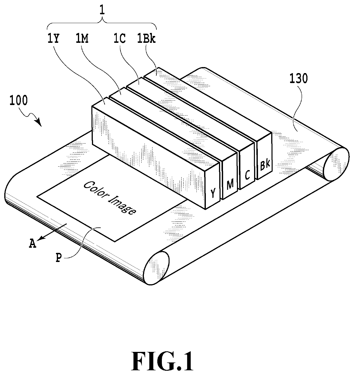
[0013]FIG. 1 is a schematic perspective view for explaining a configuration example of a liquid ejection apparatus 100 using a liquid ejection head 1. The liquid ejection apparatus 100 is what is termed a full-line type in which a long liquid ejection head 1 extending over the whole area in the width direction of a print medium P is used. A print medium P is continuously conveyed in the direction of arrow A by a conveyance mechanism 130 in which a conveyance belt, or the like, is used. An image is printed on a print medium P by ejecting ink (liquid) from the liquid ejection head 1 while the print medium P is conveyed in the direction of arrow A. In the case of the present embodiment, it is possible to print a color image by using each of the liquid ejection heads 1C, 1M, 1Y, and 1Bk that eject inks of cyan (C), magenta (M), yellow (Y), and black (K), respectively, as a liquid ejection head 1.

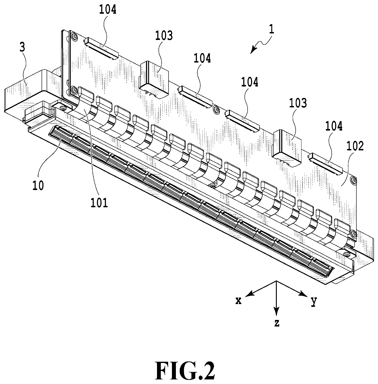
[0014]FIG. 2 is a perspective view of the liquid ejection head 1. The liquid ejection head 1...


PUM


Abstract

A liquid ejection head includes: a print element substrate including multiple ejection openings, pressure chambers, a common flow path, and pumps, the pump being configured to circulate liquid between the common flow path and the pressure chamber; and a flow path member laminated to the print element substrate. The flow path member includes a supply flow path and a collection flow path, the supply flow path being configured to supply liquid to the print element substrate, the collection flow path being configured to collect liquid that is not ejected. The supply flow path and the collection flow path have liquid connection with the same common flow path. A circulating pump generates a flow of liquid flowing in an order of the supply flow path, the common flow path, and the collection flow path, the circulating pump being provided at a position different from the print element substrate.

Description

BACKGROUND OF THE DISCLOSUREField of the Disclosure[0001]The present disclosure relates to a liquid ejection head and a liquid ejection apparatus.Description of the Related Art[0002]In a liquid ejection head used in a liquid ejection apparatus that ejects liquid such as ink, there is a possibility that ejection failure or concentration change occurs due to liquid thickening or precipitation of solid components in the vicinity of an ejection opening. In addition, bubbles or foreign substances may remain in the vicinity of an ejection opening. As a measure to attend to such problems, as disclosed in International Laid-Open No. 2012 / 015397 (hereinafter referred to as Document 1), there is a proposition of a technique in which a micropump for flowing liquid is provided inside a print element substrate so as to flow ink into a pressure chamber of the print element substrate by use of the micropump. Document 1 discloses a technique in which a micropump is incorporated in a nozzle flow pat...

Claims


Application Information

Patent Timeline
IPC IPC(8): B41J2/175B41J2/14B41J2/16
CPCB41J2/1631B41J2/14233B41J2/175B41J2/18B41J2/1404B41J2202/20B41J2202/21B41J2202/12
Inventor YAMADA, KAZUHIRONAKAGAWA, YOSHIYUKINAKAKUBO, TORUKASAI, RYOYAMAZAKI, TAKURO
Owner CANON KK
Why Eureka
Eureka Blog
Learn More