Communication apparatus
- Summary
- Abstract
- Description
- Claims
- Application Information
AI Technical Summary
Benefits of technology
Problems solved by technology
Method used
Image

Examples
second example embodiment
[0109]FIG. 27 is a schematic diagram illustrating a communication apparatus 1 of the present example embodiment. In the communication apparatus 1 of the present example embodiment, a monopole antenna (linear conductor) is used as the radio wave radiation source 10, and a metal member (conductive plate) 13 is disposed on an opposite side to control plates (the phase control plate 11 and the polarization control plate 12) with a linear conductor 14 interposed therebetween. Both of the linear conductor 14 and the metal member 13 function as the radio wave radiation source 10. The linear conductor 14 is disposed to be substantially perpendicular to the control plates (the phase control plate 11 and the polarization control plate 12). The metal member 13 is located near the linear conductor 14, and is disposed to be substantially parallel to the phase control plate. The metal member 13 also functions as a blocking member which blocks an electromagnetic wave radiated from the radio wave r...
third example embodiment
[0111]FIG. 29 is a schematic diagram illustrating a communication apparatus 1 of the present example embodiment. In the communication apparatus 1 of the present example embodiment, a monopole antenna is used as the radio wave radiation source 10. A metal member 13 is disposed on an opposite side to control plates (the phase control plate 11 and the polarization control plate 12) with a linear conductor 14 interposed therebetween. Both of the linear conductor 14 and the metal member 13 function as the radio wave radiation source 10.
[0112]In the present example embodiment, a shape of the metal member 13 is a cup shape of which a diameter gradually increases, and the linear conductor 14 is located therein. The control plates (the phase control plate 11 and the polarization control plate 12) are located to close an opening at an opening portion of the cup shape. Note that the control plates are not necessarily required to completely close the opening, and the control plates may be separ...
fourth example embodiment
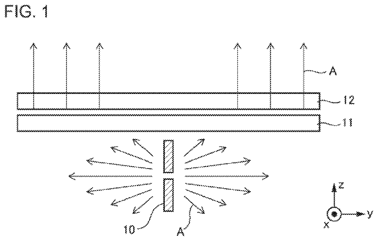
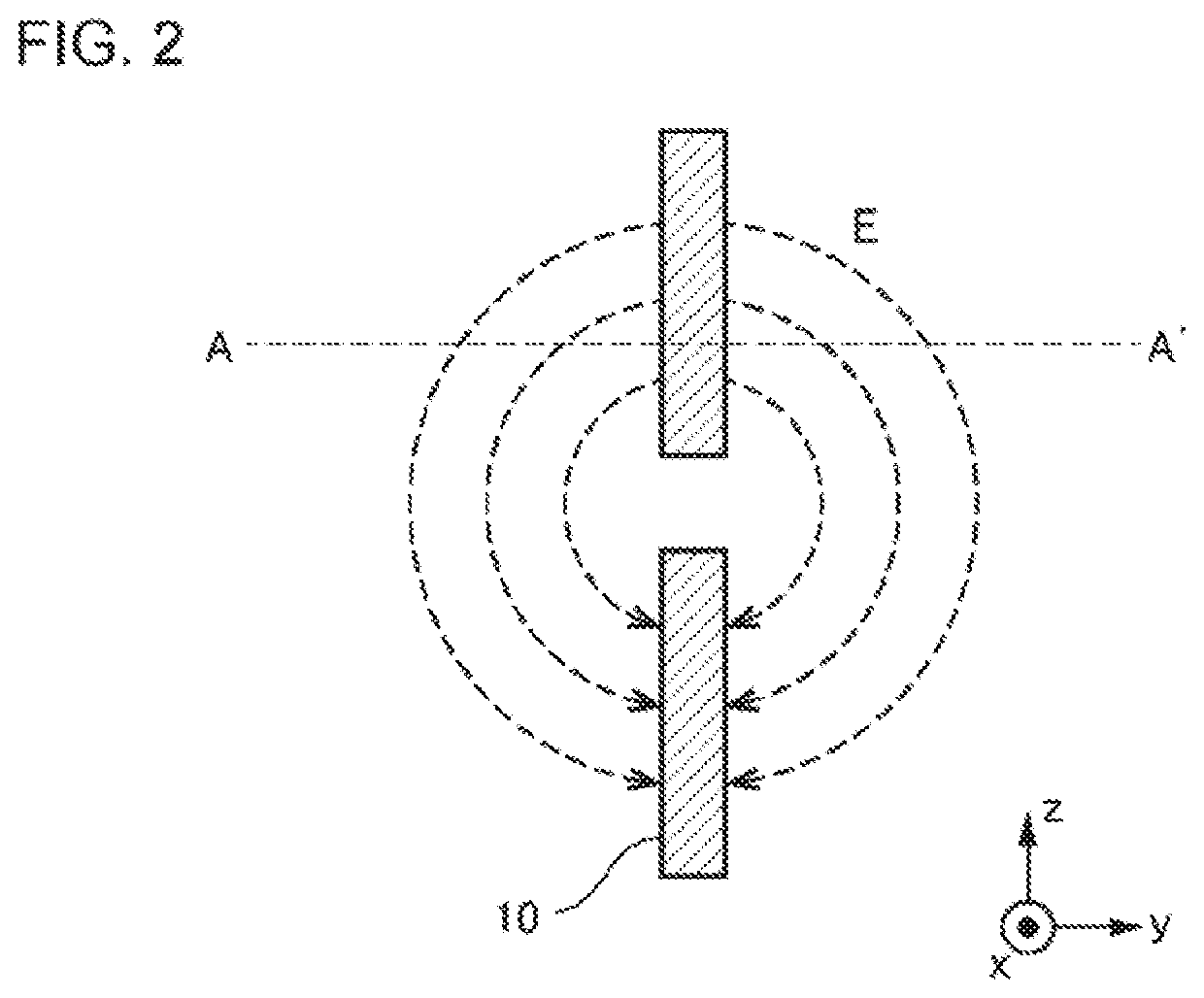
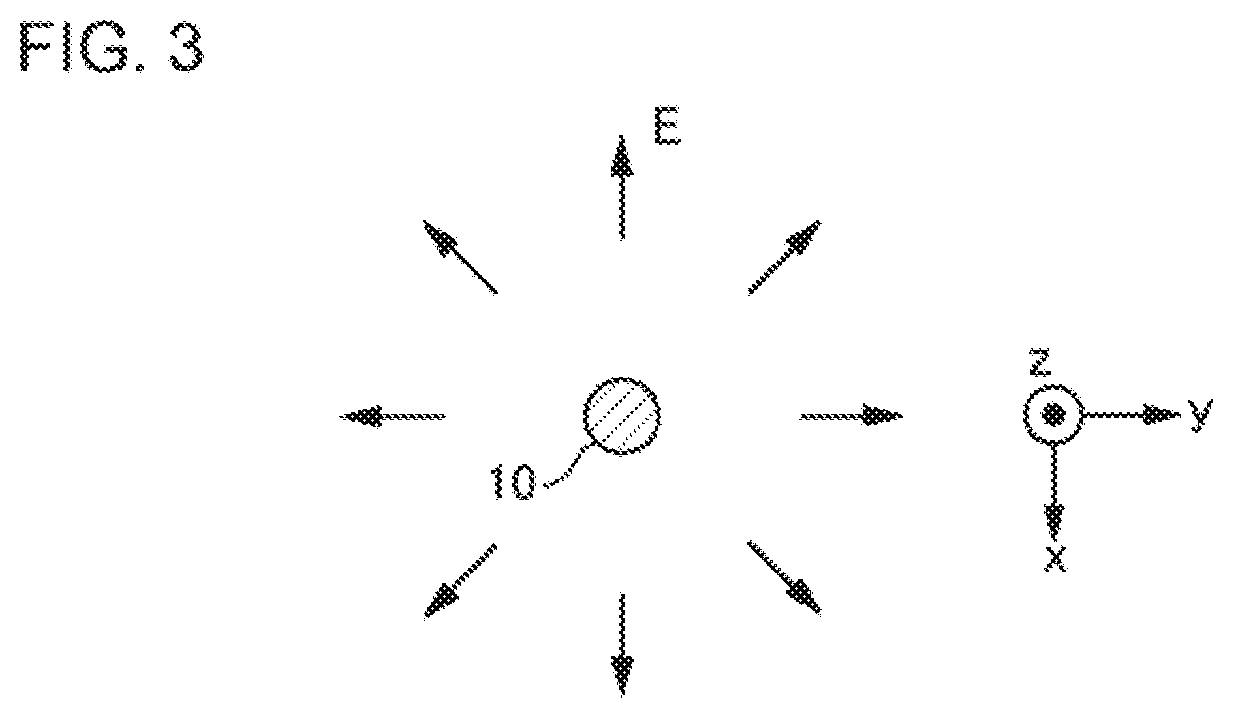
[0115]FIG. 32 is a schematic diagram illustrating a communication apparatus 1 of the present example embodiment. In the communication apparatus 1 of the present example embodiment, a small loop antenna is used as the radio wave radiation source 10. An aspect of an electric field and a magnetic field in a case where the small loop antenna is used is illustrated in FIG. 20. This is an aspect in which a magnetic field and an electric field are replaced with each other in the aspect (refer to FIGS. 2 and 3) of an electric field and a magnetic field of the dipole antenna, and shows directivity similar to that of the dipole antenna. As illustrated in FIGS. 20(A) and 20(B), the loop antenna is an antenna in which a loop is formed by a linear metal. In a case where a current as illustrated flows through the loop antenna, a magnetic field is generated as illustrated. The magnetic field is formed to surround the periphery of the linear metal (loop antenna). In other words, in the present exam...
PUM
 Abstract
Description
Claims
Application Information
 - R&D
- Intellectual Property
- Life Sciences
- Materials
- Tech Scout
- Unparalleled Data Quality
- Higher Quality Content
- 60% Fewer Hallucinations
Browse by: Latest US Patents, China's latest patents, Technical Efficacy Thesaurus, Application Domain, Technology Topic, Popular Technical Reports.
© 2025 PatSnap. All rights reserved.Legal|Privacy policy|Modern Slavery Act Transparency Statement|Sitemap|About US| Contact US: help@patsnap.com