Communication apparatus
a communication apparatus and a technology for extending antennas, applied in the direction of resonators, slot antennas, antennas, etc., can solve the problems of large communication apparatus and increase the thickness of the whole, and achieve the effect of thinning the communication apparatus
- Summary
- Abstract
- Description
- Claims
- Application Information
AI Technical Summary
Benefits of technology
Problems solved by technology
Method used
Image

Examples
first example embodiment
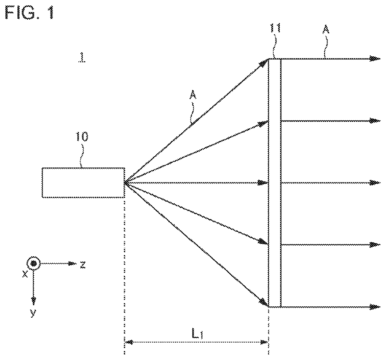
[0063]FIG. 1 is a schematic diagram illustrating a communication apparatus 1 of the present example embodiment. The communication apparatus 1 is, for example, an antenna apparatus (for example, a millimeter-wave antenna). As illustrated, the communication apparatus 1 includes a radio wave radiation source 10 and a first phase control plate 11. In the figure, an arrow A indicates an advancing direction of an electromagnetic wave. Phases of electromagnetic waves radiated from the radio wave radiation source 10 are aligned with each other by the first phase control plate 11.
[0064]The first phase control plate 11 is located at a distance L1 from the radio wave radiation source 10 in a direction (radio wave radiation direction) in which the radio wave radiation source radiates an electromagnetic wave. The radio wave radiation direction is, in electromagnetic waves radiated with a spread in a width direction toward the first phase control plate 11 from the radio wave radiation source 10, ...
second example embodiment
[0111]FIG. 27A is another example of a perspective view of a communication apparatus 1 of the present example embodiment. FIG. 27B is a view in which the communication apparatus 1 in FIG. 27A is observed in the x direction in the figure. FIG. 27C is a view in which the communication apparatus 1 in FIG. 27A is observed in the y direction in the figure.
[0112]As illustrated, the communication apparatus 1 of the present example embodiment includes a conductive plate 10C connecting the short side (refer to FIG. 8) of the slot opening 10A to the first phase control plate 11 in addition to the conductive plate 10B of the first example embodiment. Each of the conductive plate 10B and the conductive plate 10C has a diameter which gradually increases from the slot opening 10A toward the first phase control plate 11. In a case of the example illustrated in FIGS. 27A-27C, as illustrated in FIGS. 27B and 27C, both of the x direction and the y direction are blocked by the conductive plate 10B or ...
third example embodiment
[0117]FIG. 33 illustrates a configuration of the radio wave radiation source 10 of the present example embodiment. The communication apparatus 1 of the present example embodiment may not include the conductive plates 10B and 10C described in the first and second example embodiments.
[0118]Here, as illustrated in FIG. 5, in a case where the slot opening 10A is cut on a plane, a length d in the figure is required to be small. Here, d indicates a diameter of a face having the slot opening 10A, and is a diameter in a direction perpendicular to the long side of the slot opening 10A. The illustrated dslot indicates a slot length (a length of the long side of the slot). For example, d is preferably dslot×10 or less, and is more preferably dslot×5 or less. In a case where d in the figure is large, as described in the first example embodiment, power of an electromagnetic wave scatters in the x axis direction and the −x axis direction, and thus the power cannot be efficiently introduced into t...
PUM
 Abstract
Description
Claims
Application Information
PatSnap Eureka turns technology decisions into work you can execute. Powered by our Innovation Knowledge Graph, it runs expert workflows across engineering, life sciences, materials and intellectual property. Get your review-ready output in minutes.


