Retroreflectors providing information encoded in reflected non-visible laser while retaining visible light safety properties

a technology of reflected non-visible lasers and retroreflectors, applied in the direction of instruments, traffic signals, roads, etc., can solve the problems of unmet needs for devices, kits, and significant data processing and sensor overlap, and achieve the effect of improving the ability of an autonomous vehicl

Pending Publication Date: 2020-09-17
LIGHTHOUSE TECH GRP INC
View PDF3 Cites 5 Cited by
  • Summary
  • Abstract
  • Description
  • Claims
  • Application Information

AI Technical Summary

Benefits of technology

[0006]Although the use of additional signs and sign demarcations could improve the ability of an autonomous vehicle to detect and navigate byways, such features may prove distracting and unsightly to human drivers, residents, and pedestrians. As such there is a current unmet need for a device which encodes information that can be read by the sensors of an autonomous car, into elements within the current infrastructure, that do not detract from the safety of human drivers. Further, as many current signs and marking elements currently exist throughout the infrastructures of the cities around the world, there additionally exists a current unmet need for devices, kits, and methods to retrofit current signs and demarcations to include additional data for autonomous vehicles.

Problems solved by technology

Although autonomous vehicles have been programmed to sense road markers and read street signs designed for human eyes, a significant amount of data processing and sensor overlap is required to detect and garner information from such sources during the day and night, and under varying forms of light and shade.
Although the use of additional signs and sign demarcations could improve the ability of an autonomous vehicle to detect and navigate byways, such features may prove distracting and unsightly to human drivers, residents, and pedestrians.
Further, as many current signs and marking elements currently exist throughout the infrastructures of the cities around the world, there additionally exists a current unmet need for devices, kits, and methods to retrofit current signs and demarcations to include additional data for autonomous vehicles.

Method used


Image

  • Retroreflectors providing information encoded in reflected non-visible laser while retaining visible light safety properties
  • Retroreflectors providing information encoded in reflected non-visible laser while retaining visible light safety properties
  • Retroreflectors providing information encoded in reflected non-visible laser while retaining visible light safety properties

Examples


example 1

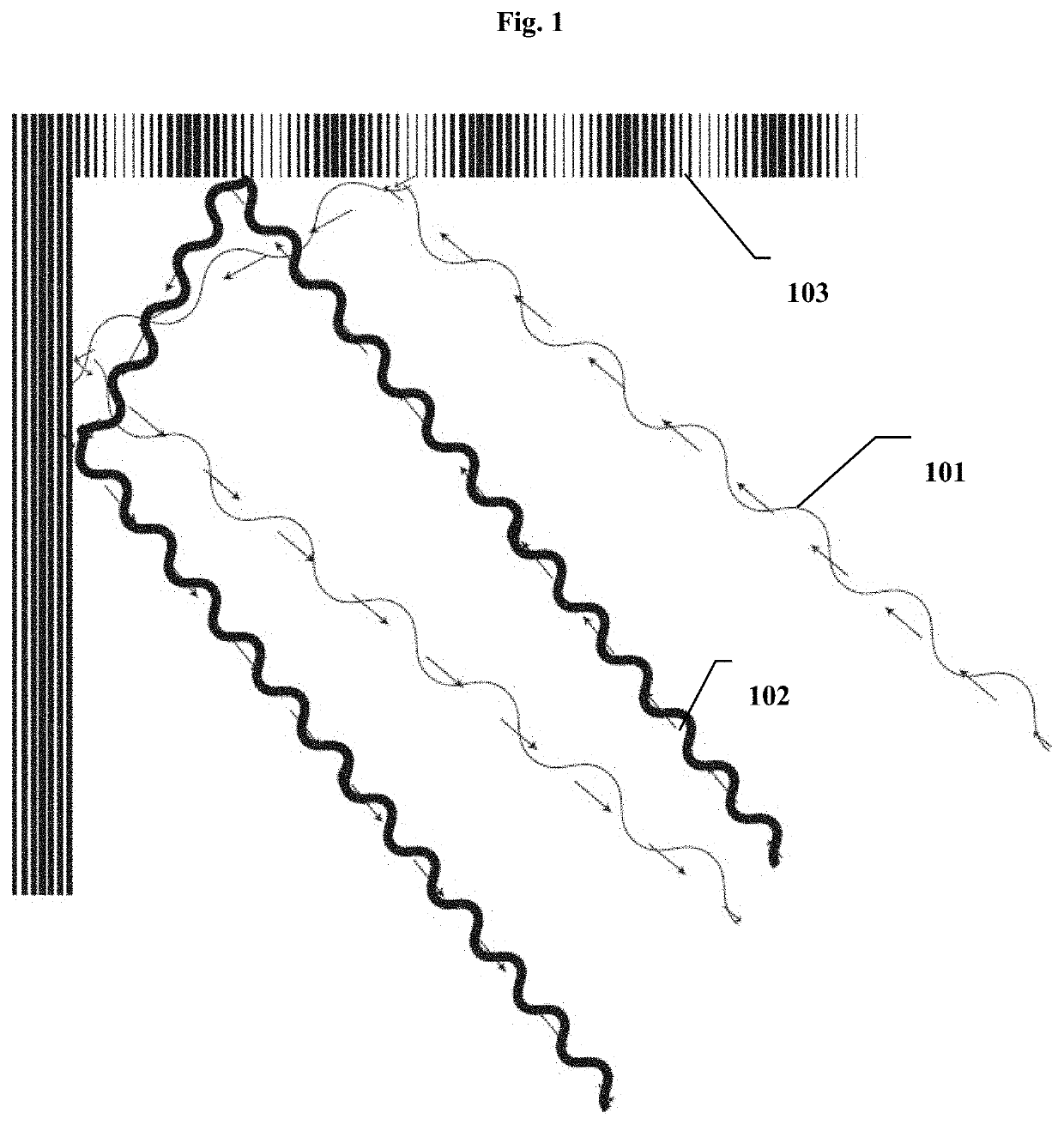
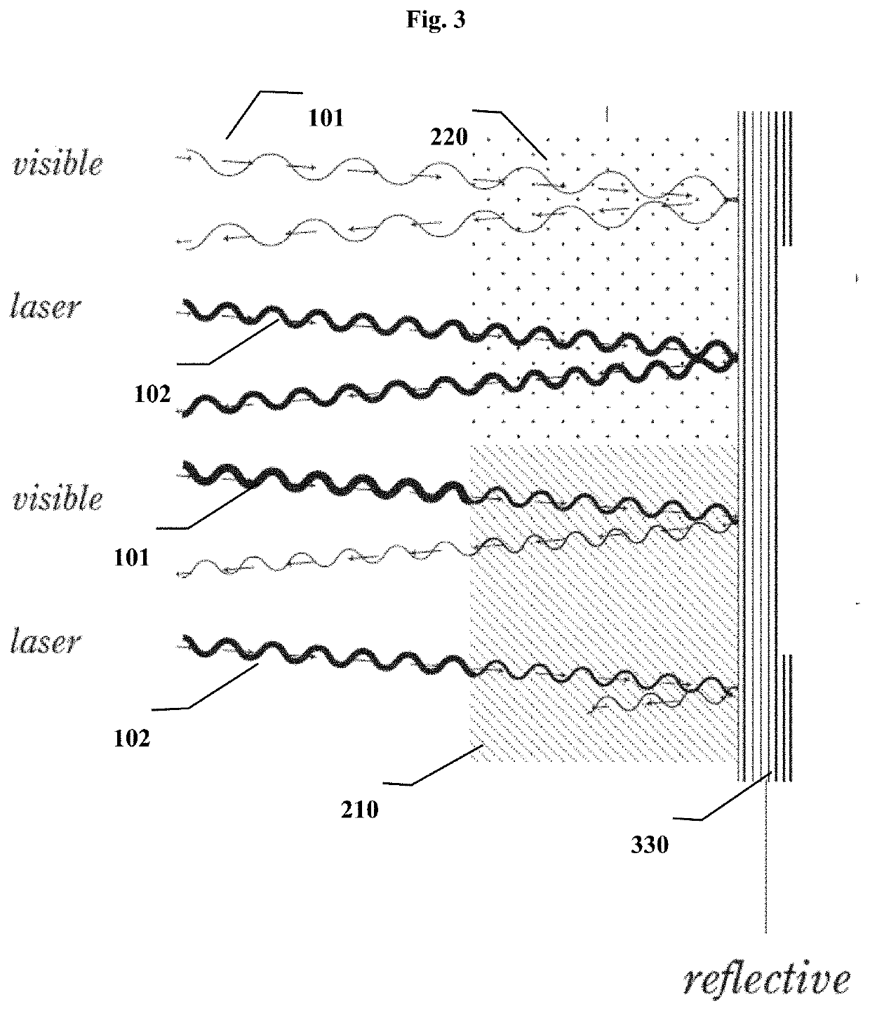
[0156]In one example, an autonomous vehicle is driving down a roadway during a rainstorm when sign visibility is low. As the vehicle approaches a sharp turn, its headlights illuminate a series of reflective markers on the road, wherein the visible light from the headlights is reflected back for the driver to see and wherein laser light outside the visible wavelength spectrum emitted from the autonomous vehicle's Light Detection and Ranging (LiDAR) system is reflected by only the reflective marker's one or more regions of the second type, wherein the reflected light is captured by the LiDAR system. A computer comprising at least one processor attached to the LiDAR system analyzes the pattern and / or shapes of the regions of the second type and determines that marker encodes a turn radius of the curve ahead. As a result, the computer instructs the vehicle to reduce its speed before the slick sharp turn ahead.

example 2

Layers of Encoding

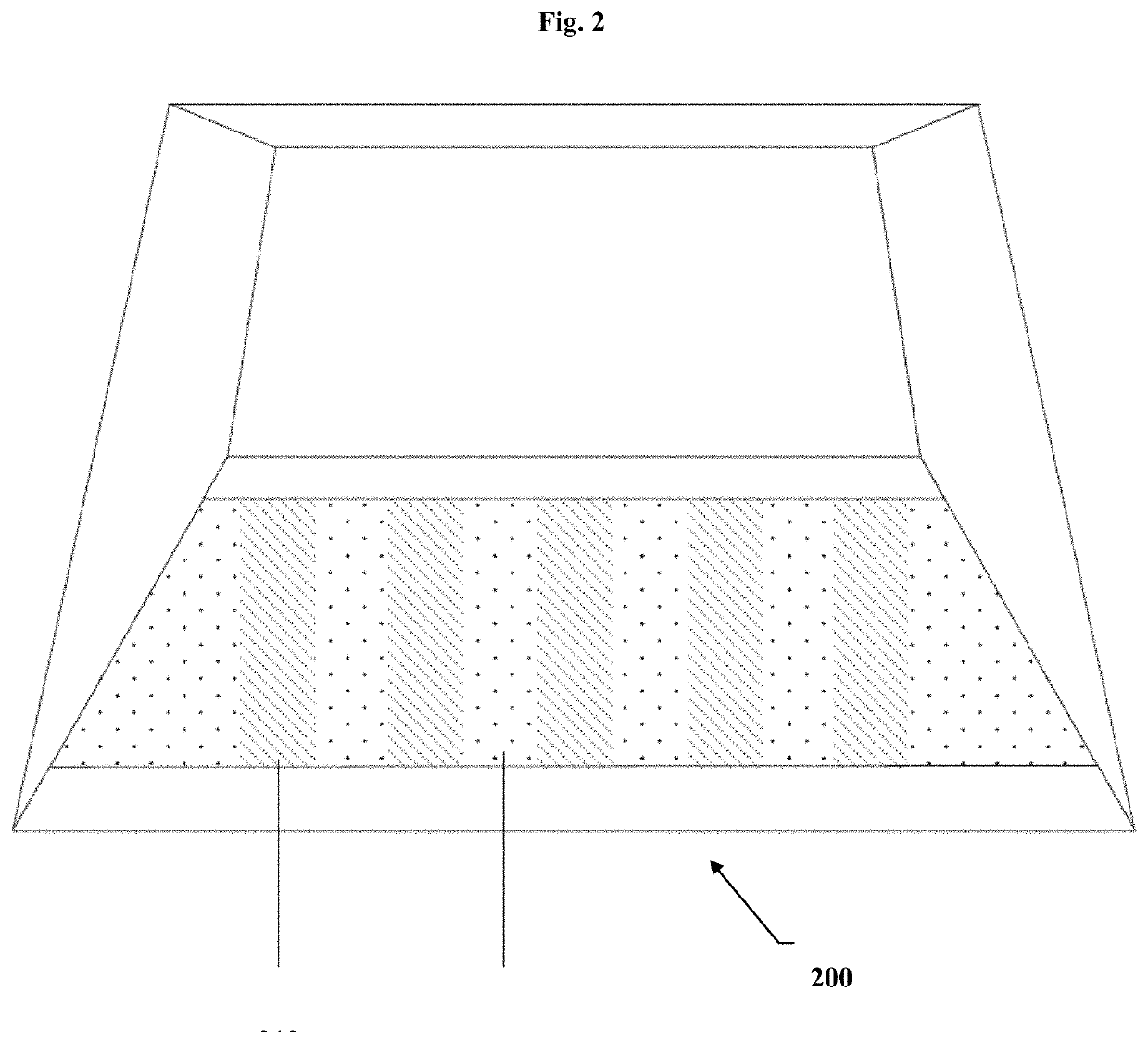
[0157]In another example, a suitable reflective marker, as shown in FIGS. 8A and 8B, comprises a retroreflective surface and a lens covering the retroreflective surface to form a left face 820, a right face 830, a top face 840, a first front face 811, a second front face 812, a third front face 813, a fourth front face 814, a fifth front face 815, a first back face 816, a second back face 817, a third back face 818, a fourth back face 819, and fifth back face 820. In one example, at least one of the faces comprises at least one of a region of the first type, a region of a second type, and a region of the third type, wherein the region of the first type comprises a first filter capable of attenuating a first laser outside the visible wavelength spectrum incident on the face, wherein the region of the second type lacks the first filter and reflecting the first laser incident on the face to its source, wherein the third filter is capable of attenuating a second laser ...

example 3

etrofitting an Existing Reflective Marker

[0162]In another example, a district wants to upgrade their current infrastructure for improved and increased use of autonomously driven cars. A worker employs a kit comprising a marker lens and an adhesive to add notifications and messages that only a LiDAR or autonomous car can read, to existing signs within the district. The worker applies the adhesive to the back of the marker lens, or removes a protective sheet from the an adhesive pre-applied to the back of the marker lens, and fastens the marker lens to a road marker, a road sign, a vehicle, an aviation runway, an aircraft, a shipping lane, a ship, a shipping container, a residential structure, a retail structure, a parking structure, or a warehouse.


PUM

PropertyMeasurementUnit
wavelengthaaaaaaaaaa

Abstract

Described are retroreflective marker devices, which encode information that can be read by optical sensors, such as LiDAR devices, and that do not detract from human safety. Also described are kits for retrofitting existing markers.

Description

CROSS-REFERENCE TO RELATED APPLICATIONS[0001]This application is a National Stage entry of PCT / US2018 / 054739, filed Oct. 5, 2018, which is a continuation-in-part of U.S. patent application Ser. No. 15 / 862,408, filed Jan. 4, 2018, now U.S. Pat. No. 10,145,993, issued Dec. 4, 2018, which further claims the benefit of U.S. Provisional Application No. 62 / 569,396, filed Oct. 6, 2017, all of which are hereby incorporated by reference.BACKGROUND OF THE INVENTION[0002]Raised pavement markers, convex vibration lines, Botts' dots, delineators, cat's eyes, road studs, or road turtles are commonly used as safety device in such commercial structures as roads, highways, buoys, docks, and runways. Raised reflective markers include materials and structures that enhance their visibility by reflecting headlights to alert a driver of locations, zones, lanes, and other route features.SUMMARY OF THE INVENTION[0003]Current reflective markers have been developed to reflect visible light emitted from the h...

Claims


Application Information

Patent Timeline
Patent Type & Authority Applications(United States)
IPC IPC(8): G02B5/12E01F9/553G01S17/02G08G1/09H04B10/112E01F9/30G01S17/74G02B5/20G02B5/124G08G1/095G01S17/931
CPCG01S17/931G01S17/74G02B5/124H04B10/112G02B5/208G08G1/09E01F9/553E01F9/30G08G1/095G01S17/02G02B5/12H04B10/1121
Inventor HADI, SURADAVIS, WILLIAMROBERTS, MICHAEL JOHN BOSWORTHANDREWS, MICHALYN
Owner LIGHTHOUSE TECH GRP INC
Why Eureka
Try Eureka