Handle

a technology for tablets and handles, applied in the field of handles, can solve the problems that the handle design of a tablet computer in military regulations cannot be universally used for all users, and the palms of some users may fail to pass through the handle,

Active Publication Date: 2020-10-08
GETAC TECH CORP
View PDF0 Cites 12 Cited by
  • Summary
  • Abstract
  • Description
  • Claims
  • Application Information

AI Technical Summary

Benefits of technology

[0004]The present invention provides a rigid handle that can be partially elastically deformed.

Problems solved by technology

However, larger palms of some users may fail to pass through the handle.
As a result, the design of a handle of a current tablet computer in military regulations cannot be universally used for all users.

Method used


Image

  • Handle
  • Handle
  • Handle

Examples


Embodiment Construction

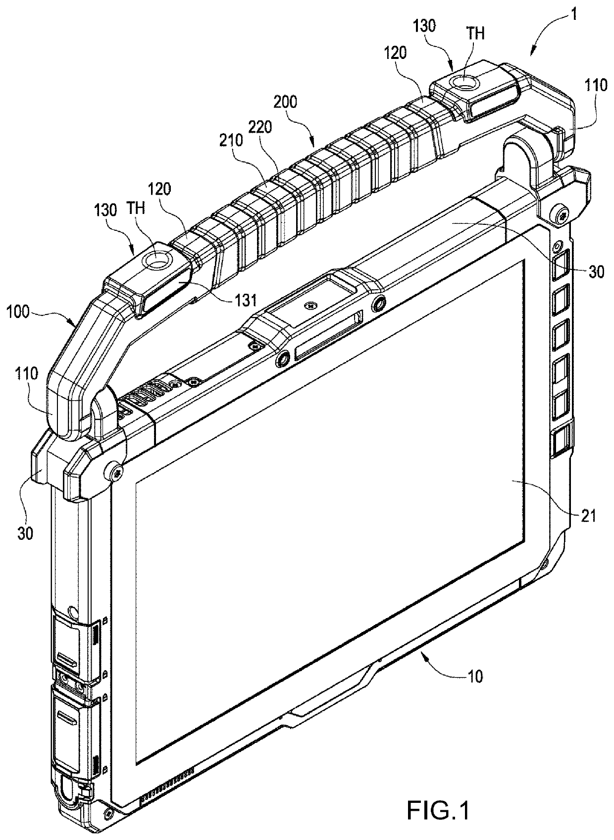
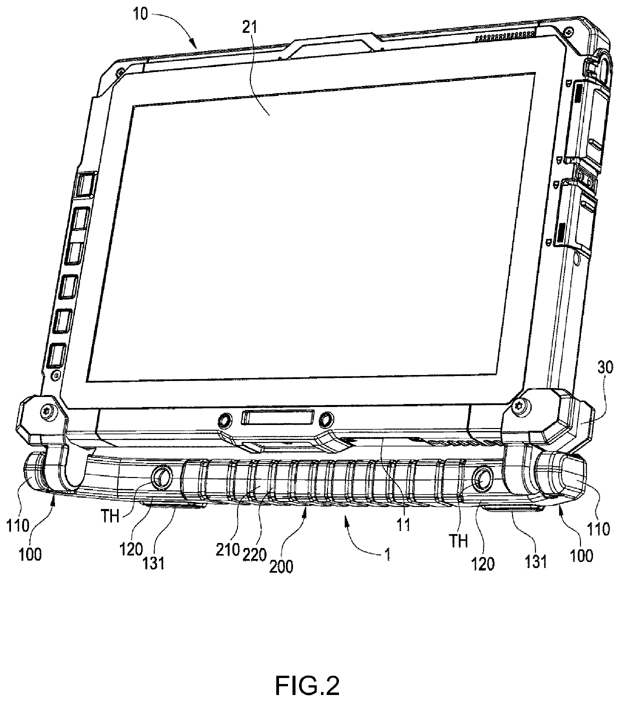
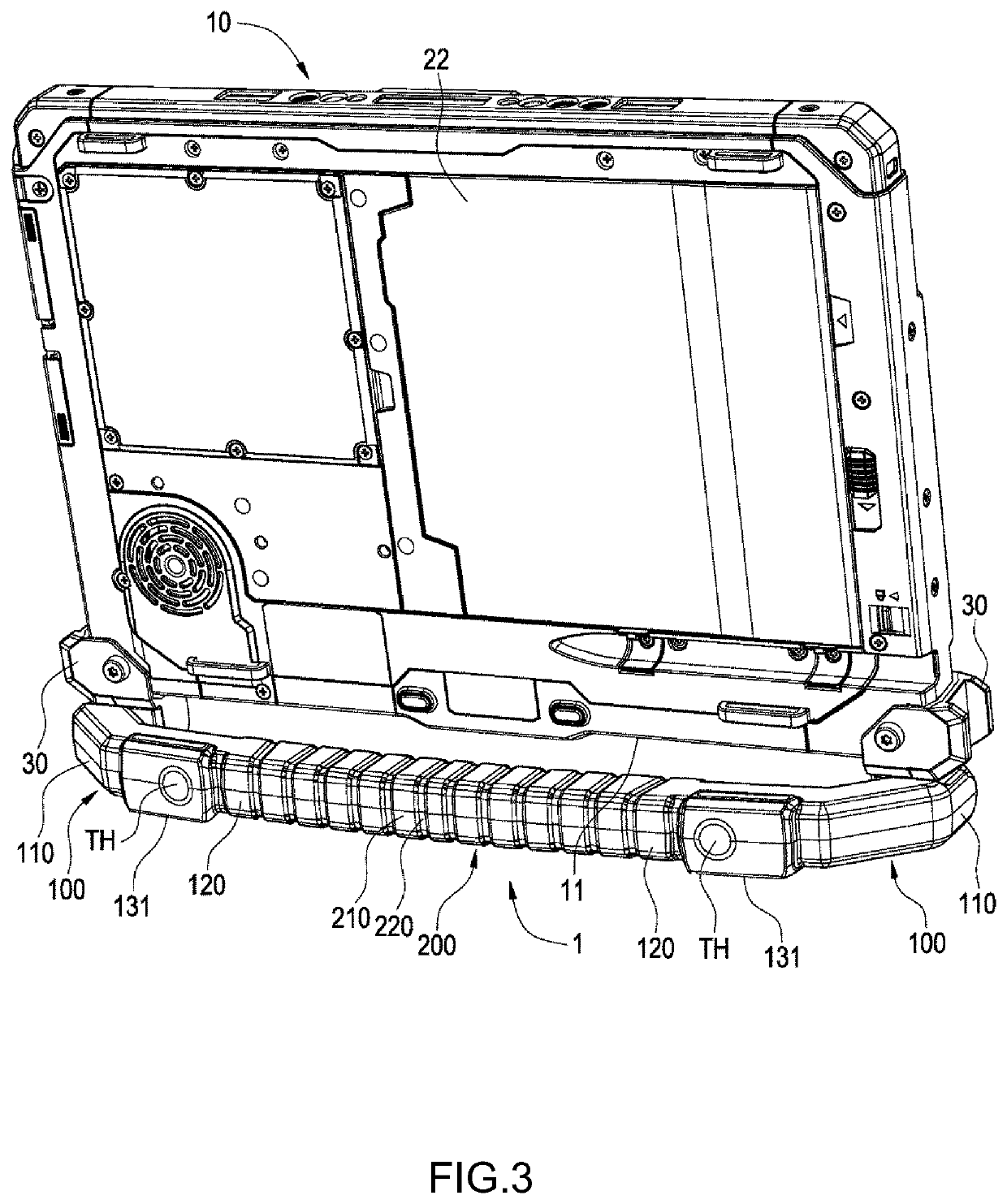
[0017]Referring to FIG. 1 to FIG. 3, a handle 1 is provided according to a preferred embodiment of the present invention. The handle 1 is pivotally configured on a mounting side 11 of an electronic device 10 to support or to hand-hold the electronic device 10. The electronic device 10 is plate-like and is preferably a tablet computer, and an electrical connection side 12 thereof is provided with an electrical connector or a plurality of electrical connection terminals for electrically connecting to a transmission dock or another electronic device. The mounting side 11 is provided on the opposite side of the electrical connection side 12 of the tablet computer. However, the present invention is not limited to the above example. Two sides of the electronic device 10 are respectively a display surface 21 and a back surface 22, and the electronic device 10 is provided with at least one stopping portion 30.

[0018]For example, as shown in FIG. 1, the handle 1 can be hand-held by a user to ...


PUM


Abstract

The present invention provides a handle adapted to be pivotally configured on a mounting side of an electronic device, and includes a pair of rigid swing arms and an elastic band. The rigid arms are individually pivotally connected on the mounting side of the electronic device along a same pivot axis. The elastic band is connected between the rigid swing arms. When the electronic device is erected on a plane, the rigid swing arms can support the weight of the electronic device. When the electronic is hand-held by a user, the elastic band can be elastically deformed to adapt to a user palm in different sizes.

Description

BACKGROUND OF THE INVENTIONField of the Invention[0001]The present invention relates to a handle for supporting an electronic device or for lifting and holding an electronic device, and more particularly to a rigid handle that can be partially elastically deformed.Description of the Prior Art[0002]A mounting side of a tablet computer in military regulations is pivotally provided with a handle for easy holding. In general, in addition for allowing a user to lift a tablet computer, the handle can also be used to support the tablet computer to erect the tablet computer on a table top. Thus, handles are mostly made of materials having higher rigidity to provide a sufficient support force. When a user holds the foregoing mounting side of a tablet computer, a user passes a palm thereof between a gap between the handle and the mounting side. However, larger palms of some users may fail to pass through the handle. If the gap between the handle and the mounting side is enlarged to adapt to u...

Claims


Application Information

Patent Timeline
Patent Type & Authority Applications(United States)
IPC IPC(8): F16M13/00A45F5/10G06F1/16F16M13/02F16M11/10
CPCA45F2200/0525F16M11/10F16M13/005A45F5/10A45F2005/002F16M2200/065G06F1/1656G06F1/1626F16M13/022A45C13/28A45C2011/003A45C2200/15F16M2200/08G06F1/166G06F2200/1633
Inventor ZHONG, SHI-LIANGCHIANG, CHENG-HUNG
Owner GETAC TECH CORP
Why Eureka
Try Eureka