Cutout mounted recloser

a recloser and mounting plate technology, applied in the direction of circuit-breaking switch details, protective switch operating/release mechanisms, relays, etc., can solve the problems of recloser and associated electronics not being able to receive primary electrical power for relatively prolonged periods, recloser and associated electronics can not receive primary electrical power for relatively long periods, and the recloser remains in the open position. , to achieve the effect of increasing the linear distan

Active Publication Date: 2020-10-15
ABB (SCHWEIZ) AG
View PDF0 Cites 0 Cited by
  • Summary
  • Abstract
  • Description
  • Claims
  • Application Information

AI Technical Summary

Benefits of technology

[0004]An aspect of an embodiment of the present application is a cutout mountable recloser that includes a first terminal and a recloser assembly, the recloser assembly being electrically coupled to the first terminal. The recloser assembly can include a current interrupter, an electromagnetic actuator, and a pushrod. The recloser can further include a latch system that is coupled to the recloser assembly. The latch system can comprise a lower terminal latch plate that is pivotally displaceable between a first, raised position and a second, lowered position. The recloser can also include a second terminal that is electrically coupled to the recloser assembly, and which is coupled to the lower terminal latch plate. The second terminal can be pivotally displaceable between a raised position and a lowered position by the pivotable displacement of the lower terminal latch plate between the first, raised position and the second, lowered position. Additionally, the second terminal can be separated from the first terminal by a first linear distance when the second terminal is in the raised position, and by a second linear distance when the second terminal is in the lowered position, the first linear distance being smaller than the second linear distance.
[0005]Another aspect of an embodiment of the present application is a recloser that is structured for a selectively releasable latching engagement with a cutout. The recloser can include a driver, a first terminal, and a recloser assembly, the recloser assembly being electrically coupled to the first terminal and coupled to the driver. The recloser assembly can include a current interrupter, a pushrod, an electromagnetic actuator, and a closing mechanism. The closing mechanism can have at least one closer body and at least one mechanical biasing element. The at least one mechanical biasing element can release a force, when the closing mechanism is discharged from a charged state to a discharged state, that displaces the at least one closer body into a moving engagement with the pushrod. The moving engagement between the at least one closer body and the pushrod can displace the pushrod to a position that electrically closes the current interrupter. The recloser can also include a latch system that is coupled to the driver. The latch system can have a lower terminal latch plate that is pivotally displaceable in between a first, raised position and a second, lowered position. Additionally, the recloser can include a second terminal that can be coupled to the lower terminal latch plate and electrically coupled to at least the recloser assembly. The second terminal can be pivotally displaceable between a raised position and a lowered position by the pivotable displacement of the lower terminal latch plate between the first, raised position and the second, lowered position.
[0006]Another aspect of an embodiment of the present application is a method that includes rotably coupling a second terminal of a recloser to a lower hinge support of a cutout, the recloser including an electromagnetic actuator. A first terminal of the recloser can then be rotably displaced into engagement with an upper contact of an upper mounting bracket of the cutout. The recloser can be latched to the cutout by selectively increasing a linear distance between the first terminal and the second terminal via at least rotation of a driver of the recloser in a first rotational direction. Each of the preceding steps can, for example, be performed while the recloser is in an electrically opened condition. Moreover, according to certain embodiments, the recloser may not be closed until after the recloser has been latched to the cutout. Further, the recloser can be unlatched from the cutout by selectively decreasing the linear distance between the first terminal and the second terminal via at least rotation of the driver in a second rotational direction. Additionally, after unlatching the recloser, the first terminal can be rotably displaced from the upper contact.

Problems solved by technology

Yet, at least in certain situations, the recloser and associated electronics can cease to receive a supply of primary electrical power for relatively prolonged periods of time.
Such unavailability of primary power can result in a depletion of stored electrical power for operation of the recloser.
Accordingly, the stored electrical power, if any, can become insufficient to effectuate operation of the recloser, which can result in the recloser remaining in the open position.

Method used


Image

  • Cutout mounted recloser
  • Cutout mounted recloser
  • Cutout mounted recloser

Examples


Embodiment Construction

[0037]Certain terminology is used in the foregoing description for convenience and is not intended to be limiting. Words such as “upper,”“lower,”“top,”“bottom,”“first,” and “second” designate directions in the drawings to which reference is made. This terminology includes the words specifically noted above, derivatives thereof, and words of similar import. Additionally, the words “a” and “one” are defined as including one or more of the referenced item unless specifically noted. The phrase “at least one of” followed by a list of two or more items, such as “A, B or C,” means any individual one of A, B or C, as well as any combination thereof.

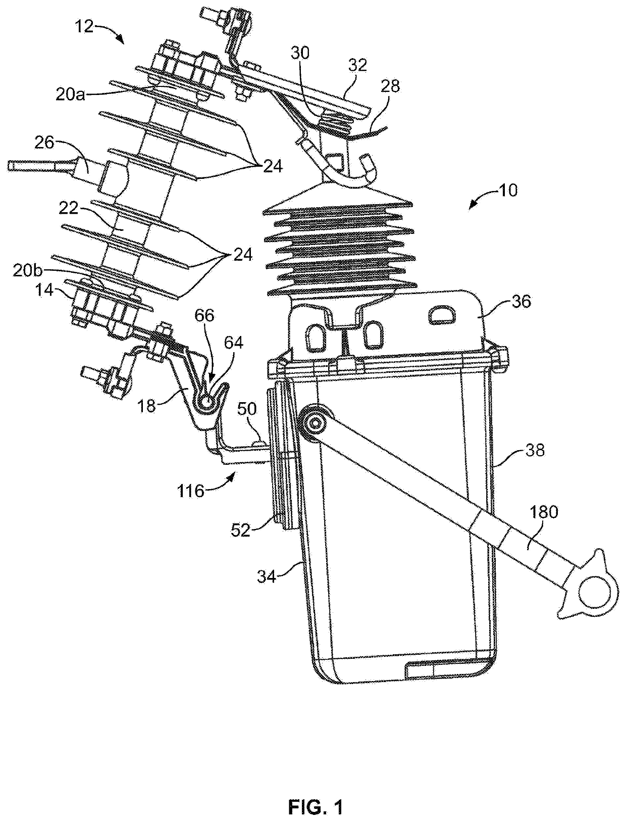
[0038]FIG. 1 illustrates a side view of a cutout mountable recloser 10 latched to a cutout 12 according to an exemplary embodiment of the present application. The cutout 12 can, for example, be used for overhead power distribution systems. According to the illustrated embodiment, the cutout 12 includes a support bracket 14 having an upper mountin...


PUM


Abstract

A cutout mountable recloser that remains latched to the cutout until the recloser is selectively mechanically unlatched via at least rotation of a driver by an operator. During installation, including while the recloser is being latched to the cutout, the recloser can be in an open condition. Latching of the recloser to the cutout can include increasing a tension force exerted by the cutout on the recloser by increasing a linear distance between first and second terminals of the recloser. With the opened recloser latched to the cutout, the recloser can be mechanically closed via a release of stored energy from a closing mechanism. The recloser can selectively be mechanically unlatched from the cutout by a subsequent reduction in the linear distance between first and second terminals of the recloser, which can reduce the tension force being exerted by the cutout.

Description

BACKGROUND[0001]Embodiments of the present application generally relate to recloser devices for power distribution systems. More particularly, but not exclusively, embodiments of the present application relate to reclosers that are latchable to cutouts in an open condition, and which in the absence of selective mechanical unlatching remain latched to the cutout regardless of the open or closed condition of the recloser or its operational state or history.[0002]Fuse cutouts, or simply cutouts, are used to protect against electrical overload in power distribution systems. Traditional cutout designs often employ a high voltage dropout fuse and a mounting insulator that electrically isolates conductive portions of the cutout from the support to which the cutout is mounted. Often, an end of the dropout fuse is pivotally attached to the cutout, while the other end of the dropout fuse is configured to be releasable from the cutout upon the occurrence of certain electrical events, such as, ...

Claims


Application Information

Patent Timeline
Patent Type & Authority Applications(United States)
IPC IPC(8): H01H71/24H01H50/14H01H50/64
CPCH01H71/24H01H50/641H01H50/14H01H75/04H01H33/6662H01H33/125H01H33/42
Inventor HANNA, ROBERT L.FISCHER-CARNE, PATRICK R.DI MAIO, LUCIANO A.
Owner ABB (SCHWEIZ) AG
Why Eureka
Try Eureka