
Control device for automatic transmission and control method for automatic transmission

a technology of automatic transmission and control device, which is applied in the direction of gearing control, gearing element control, belt/chain/gearing, etc., can solve the problems of unnatural feeling and inability of vehicle behavior, and achieve the effect of suppressing the giving of unnatural feeling to the driver

Active Publication Date: 2020-12-24
JATCO LTD +1
View PDF0 Cites 0 Cited by
  • Summary
  • Abstract
  • Description
  • Claims
  • Application Information

AI Technical Summary

Benefits of technology

The present invention aims to improve the driving experience during auto-upshifts in a lock-up engaged state by preventing an unnatural feeling for the driver when releasing the accelerator foot. This is achieved by keeping the lock-up clutch engaged and performing a forced downshift. The technical effect is improved driving comfort and a more natural feeling for the driver.

Problems solved by technology

From this state, when the driver presses down again, since the lock-up clutch is released, there was the problem of engine rotation blow-up, and the vehicle behavior was not able to respond to the acceleration intention of the driver, giving the driver an unnatural feeling.

Method used


Image

  • Control device for automatic transmission and control method for automatic transmission
  • Control device for automatic transmission and control method for automatic transmission
  • Control device for automatic transmission and control method for automatic transmission

Examples


embodiment 1

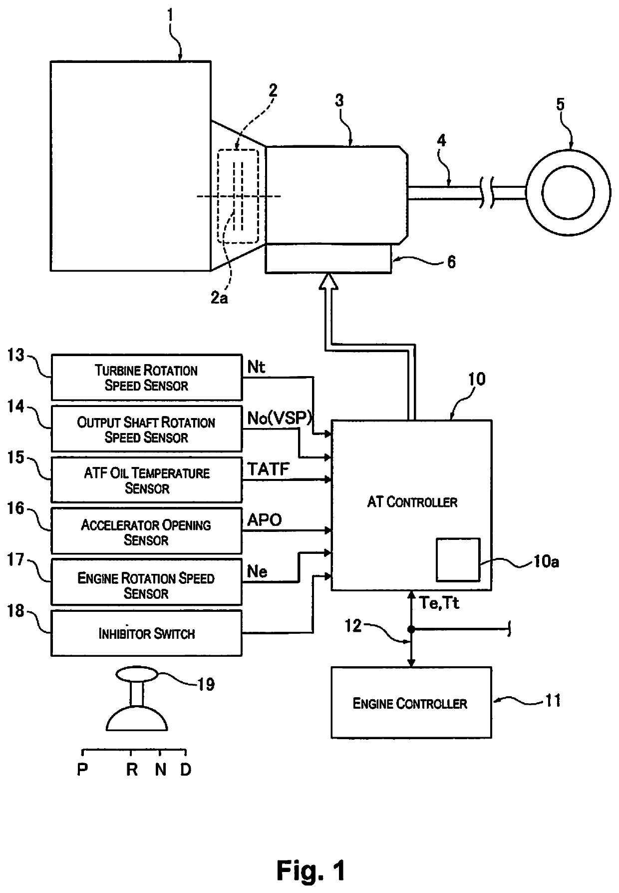
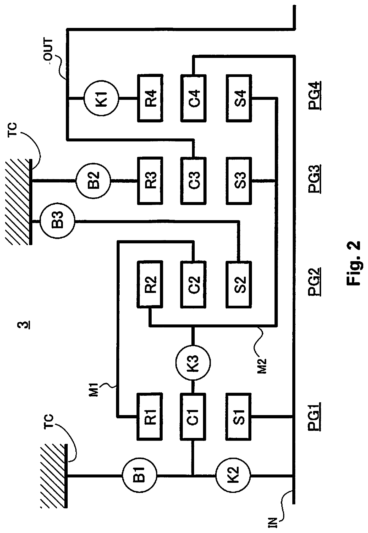
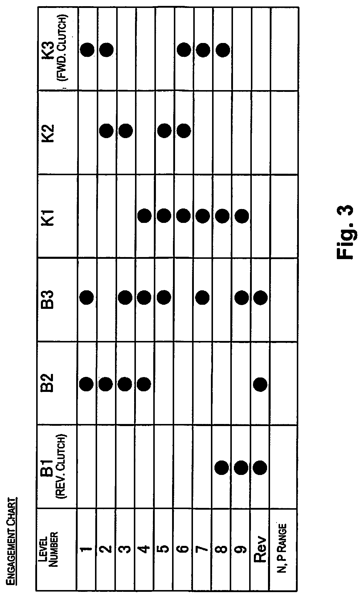
[0017]A control device of Embodiment 1 is applied to an engine car (example of a vehicle) in which is mounted an automatic transmission comprising a torque converter with a built in lock-up clutch and a stepped transmission mechanism that achieves gear levels of nine forward gears and one reverse gear. Hereafter, the configuration of Embodiment 1 is explained divided into “Overall System Configuration,”“Detailed Configuration of Stepped Transmission Mechanism,” and “Forced Downshift Control Processing Mechanism.”

Overall System Configuration

[0018]FIG. 1 is an overall system configuration drawing of an engine car in which is mounted an automatic transmission to which is applied the control device of Embodiment 1. Following, the overall system configuration is explained based on FIG. 1.

[0019]As shown in FIG. 1, provided in the drive system of the engine car are an engine 1, a torque converter 2 with a built in lock-up clutch 2a, a stepped transmission mechanism 3, a propeller shaft 4, ...


PUM


Abstract

A control device for an automatic transmission arranged between an engine and a drive wheel, the automatic transmission including a torque converter having a lock-up clutch, and a transmission mechanism. The control device includes a shift control unit configured to perform shift control of the transmission mechanism. The shift control unit includes a forced downshift control processing unit configured to implement forced downshift when an accelerator foot release operation is performed during auto-upshift in a power-on state with the lock-up clutch engaged. The forced downshift control processing unit is configured to start the forced downshift before an engine rotation speed that has decreased due to the auto-upshift reaches a lock-up release rotation speed.

Description

[0001]This is a U.S. national phase application of PCT / JP2019 / 007722, filed on Feb. 28, 2019, which claims priority to Japanese Patent Application No. 2018-047396, filed on Mar. 15, 2018. The entire disclosure of Japanese Patent Application No. 2018-047396 is hereby incorporated herein by reference.TECHNICAL FIELD[0002]The present invention relates to a control device for an automatic transmission mounted in a vehicle and a control method for an automatic transmission.BACKGROUND ART[0003]Conventionally, to address the problem of realizing an upshift shift that suppresses busy-shift, described is a control device for an automatic transmission for a vehicle that executes shift delay processing when it is possible that a kick down operation with a relatively large accelerator return amount may be performed (see Japanese Laid-Open Patent Application Publication No. 2012-149726).SUMMARY[0004]With the abovementioned prior art device, when in a coast state by an accelerator return operatio...

Claims


Application Information

Patent Timeline
IPC IPC(8): F16H61/16F16H59/18F16H59/44F16H59/48F16H59/56
CPCF16H59/56F16H59/48F16H61/16F16H59/18F16H2059/366F16H59/44F16H2061/161F16H61/143
Inventor HIRASAKO, KAZUKI
Owner JATCO LTD
Learn More