
Control device for continuously variable transmission

a control device and transmission technology, applied in the direction of gearing control, gearing elements, gearing, etc., can solve the problems of oil vibration being generated, and achieve the effect of preventing mutual increase and reducing the variation of control hydraulic pressur

Active Publication Date: 2017-07-20
JATCO LTD +1
View PDF2 Cites 5 Cited by
  • Summary
  • Abstract
  • Description
  • Claims
  • Application Information

AI Technical Summary

Benefits of technology

This patent relates to a control device for a continuously variable transmission. The objective is to address issues such as unnatural feelings for the driver and variations in vehicle behavior. The device ensures that the oil vibration is minimized and the pilot pressure is stable, resulting in a decrease in the variation of the control hydraulic pressure. As a result, the device prevents an increase in the hydraulic circuit and avoids unnatural feelings for the driver.

Problems solved by technology

When the control to increase the hydraulic pressure is performed when the line pressure is lower than the first predetermined pressure which is the pilot pressure, the oil vibration may be generated due to the hydraulic pressure increase command.

Method used


Image

  • Control device for continuously variable transmission
  • Control device for continuously variable transmission
  • Control device for continuously variable transmission

Examples


Embodiment Construction

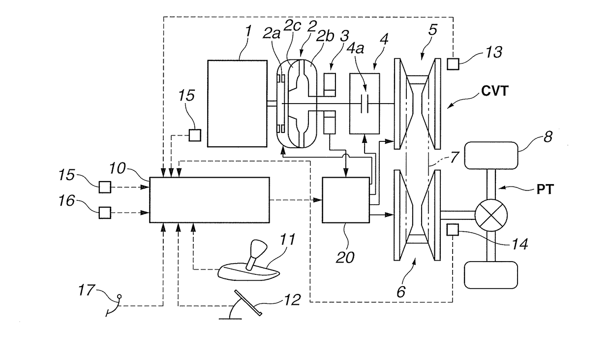
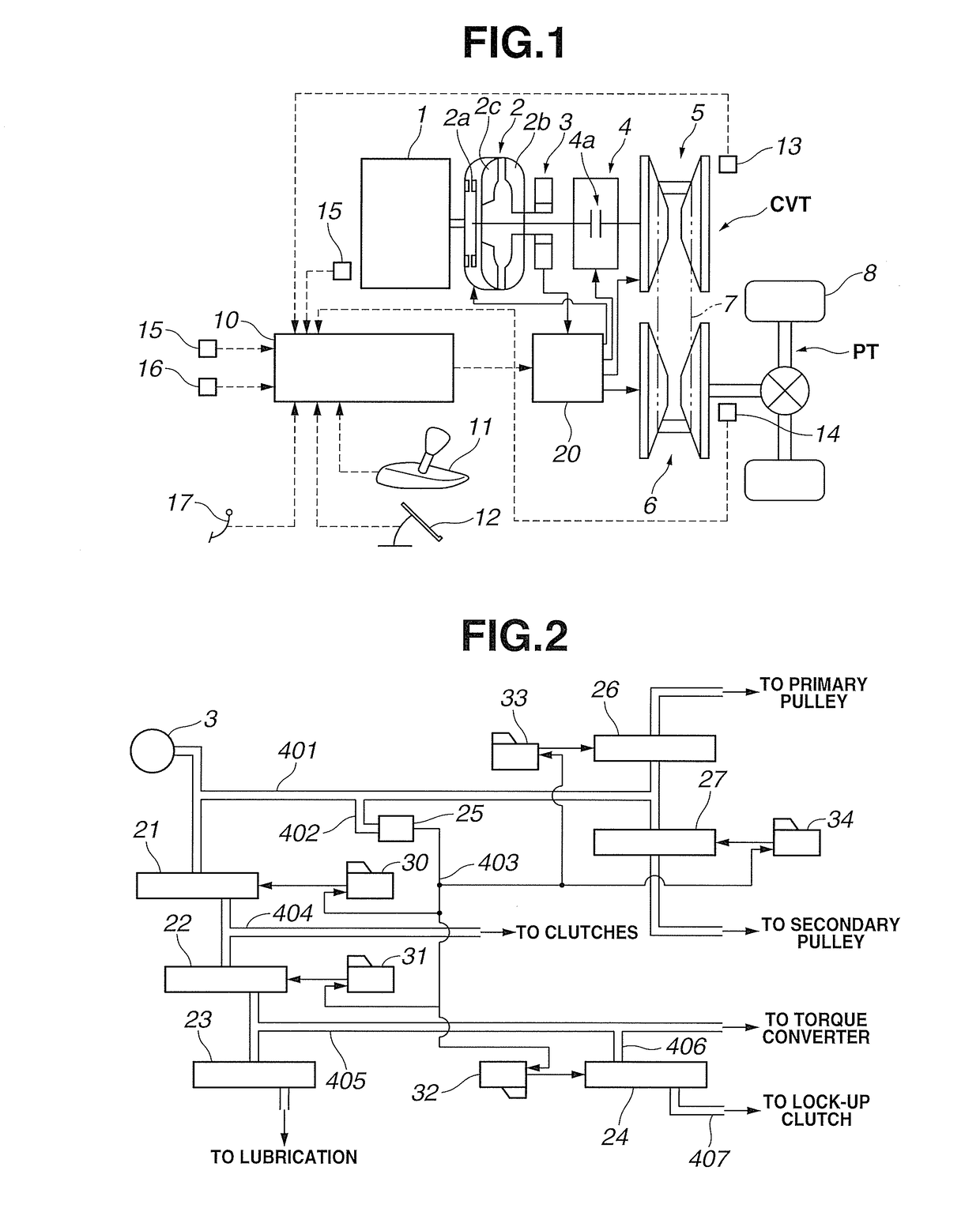
[0015]FIG. 1 is a system diagram showing a control device of a continuously variable transmission according to a first embodiment. A vehicle according to the first embodiment includes an engine 1 which is an internal combustion engine, and the continuously variable transmission. A driving force is transmitted through a differential gear to tires 8 which are driving wheels. A power transmitting path connected from a belt type continuously variable transmission mechanism CVT to the tires 8 is referred to as a power train PT.

[0016]The continuously variable transmission includes a torque converter 2, an oil pump 3, and a forward / rearward movement switching mechanism 4, and the belt type continuously variable transmission mechanism CVT. The torque converter 2 includes a pump impeller 2b connected to the engine 1, and arranged to rotate as a unit with a driving claw configured to drive the oil pump 3; a turbine runner 2c connected to an input side of the forward / rearward movement switchin...


PUM


Abstract

A control device for a continuously variable transmission includes: a line pressure generating-section configured to generate a line pressure; a pilot valve configured to supply a pilot pressure regulated so as not to exceed a first predetermined pressure when the line pressure exceeds the first predetermined pressure; a control section configured to generate the clamping forces by controlling the pilot pressure; a line pressure increase section configured to increase the line pressure to be greater than the first predetermined pressure when the control to increase the line pressure is performed when the line pressure is lower than the first predetermined pressure.

Description

TECHNICAL FIELD[0001]This invention relates to a control device for a continuously variable transmission mounted on a vehicle.BACKGROUND ART[0002]In a belt type continuously variable transmission, when a foot brake switch (hereinafter, referred to as a brake switch) is brought to an ON state by a depression of a brake pedal, a braking torque is transmitted from driving wheels to the continuously variable transmission, so that a belt slippage may be generated. A patent document 1 discloses an art to prevent the belt slippage by increasing a belt clamping force of the continuously variable transmission when the brake switch is brought to the ON state.[0003]In recent years, a hydraulic control of the transmission is often performed in a state where a line pressure is set to a low value, for improving fuel economy. In a case where the brake switch becomes the ON state when a vehicle travels in a state where the line pressure is lower than a pilot pressure that is a source pressure of a ...

Claims


Application Information

Patent Timeline
IPC IPC(8): F16H61/662F16H9/16F16H59/44F16H59/54F16H59/48
CPCF16H61/66272F16H59/54F16H2061/66277F16H59/44F16H9/16F16H59/48F16H61/662F16H61/0021F16H2312/18F16H61/02
Inventor HONMA, TOMOAKISUZUKI, YUTASHINOHARA, ITARUSEKIYA, HIROSHIOGINO, HIROMU
Owner JATCO LTD
Learn More