Syringe for one-handed injection and aspiration

a one-handed, injection technology, applied in the field of syringes, can solve the problems of unsatisfactory two-handed operation, preventing a user from conveniently using a single configuration for both injection and aspiration, and reducing so as to reduce the risk of use, increase the accuracy of aspirated sample volume, and ensure the effect of injection and aspiration

Active Publication Date: 2020-12-31
ALSAHAB MEDICAL CO
View PDF0 Cites 0 Cited by
  • Summary
  • Abstract
  • Description
  • Claims
  • Application Information

AI Technical Summary

Benefits of technology

[0024]The syringe structure described herein uses minimal components that are combined in a particular way to provide a safe and easy injection and aspiration with a one-hand technique. The device increases the accuracy of aspirated sample volume, as well as maintain consistent physical at the location of the sample place, such as when accessing a deep vein. In addition, the structure reduces the risks and complications of using both hands in emergency situations, i.e. bleeding due to multiple punctures to the vessels; and this is a critical in severely injured patients, especially when accessing deep veins.
[0025]Other than in the medical field, this syringe is also useful to laboratory technicians when aspirating samples from test tubes and is a convenient replacement to a bulb syringe for doing so. It also allows for easy aspiration of syrup medications from bottles by enabling the user to hold the bottle in one hand and the syringe with the other. For instance, mothers who are administering medicines to their child.

Problems solved by technology

Two-handed operation is not ideal because the user may very well want to use the other hand for another task, such as holding a bottle from with the liquid is withdrawn.
While devices such as that described above in U.S. Pat. No. 4,484,915 allow for a one-handed aspiration operation, it does so by integrating a complex three part structure with a syringe, and prevents a user from conveniently using a single configuration for both injection and aspiration.
Moreover, the multiple axial extending members move along an outer surface of the syringe which makes it difficult for the user to position their index and middle fingers in normal positions about the syringe barrel because the multiple axial extending members can too easily rub against one, or both, of the users fingers.
With regard to the device in U.S. Pat. No. 1,221,103 the present inventor recognized that syringe external plunger arms are unsupported, and the internal plunger arm is in the middle, which might cause the user's thumb to slide away from the handle especially in small-sized injections, making its safety questionable.
Furthermore, a prominence along with the plunger's handles; might provide discomfort to one or more of the operator fingers.
Also, the internal cylindrical plunger rod will be adherent into the inner surface of the cylindrical wall, which will make the aspiration unsafe as it interferes with the thumb while aspirating.
In addition, needle stability might be compromised during aspiration process, which, in turn, will cause problems such as hemorrhage, for example.
Thus, this structure limits its applicability in critical situations and narrow places because of its elongated structure.

Method used


Image

  • Syringe for one-handed injection and aspiration
  • Syringe for one-handed injection and aspiration
  • Syringe for one-handed injection and aspiration

Examples


Embodiment Construction

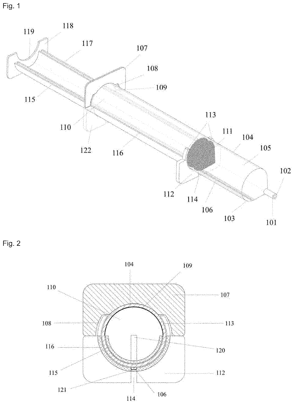
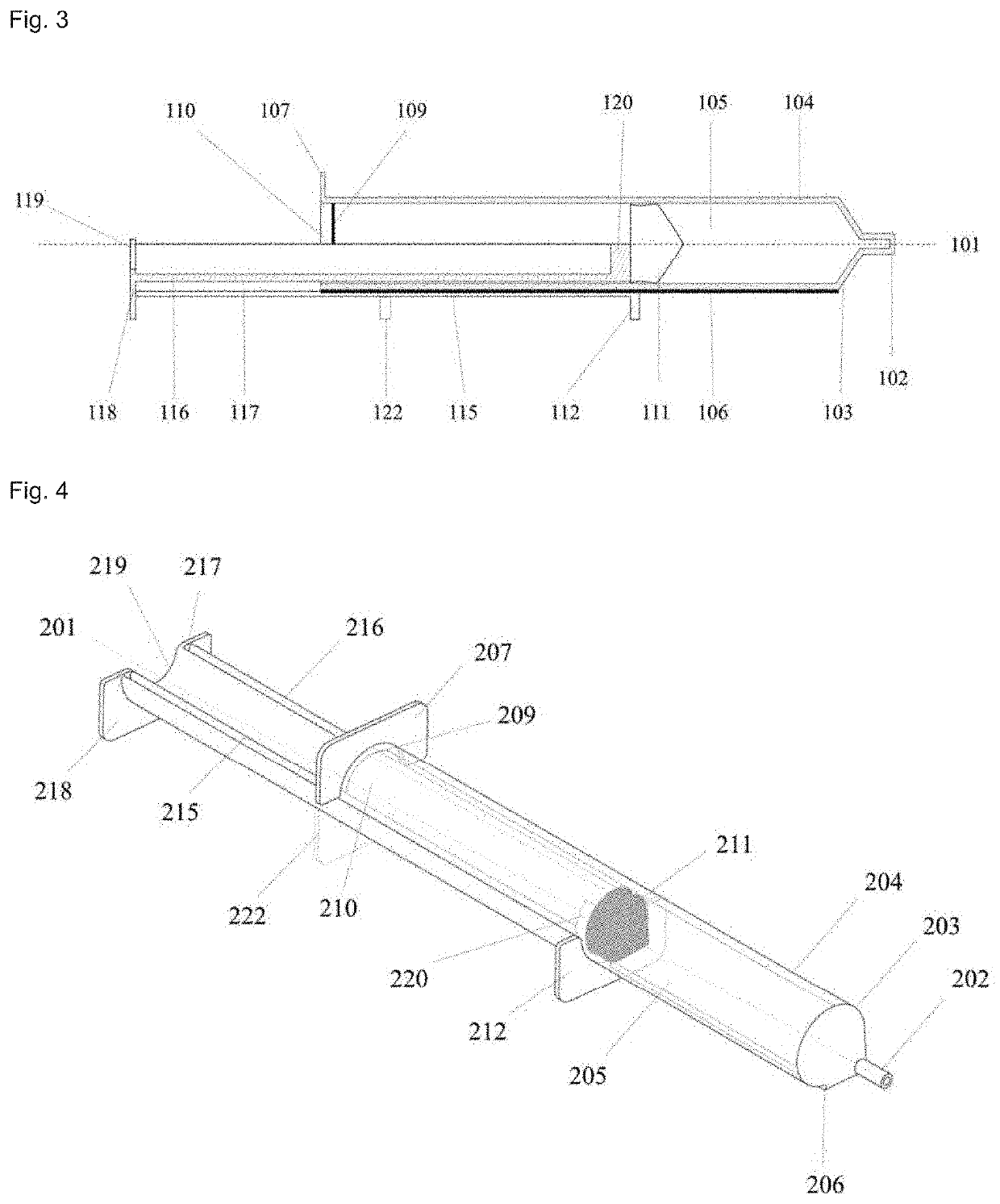
[0033]For a first embodiment, “Model (A)” is described with reference to FIGS. 1, 2 & 3 and include the following components: [102], [103], [104], [105], [106], [107], [108], [109] and [110] are all associated with a cylinder, and components: [111], [112], [113], [114], [115], [116], [117], [118], [119], [120], [121] and [122] are all associated with a plunger.

[0034]FIG. 1 shows a hollow cylinder body [104] with a conically shaped front (anterior) end [103] which ends with a frontal syringe tip (or frontal tip) [102] that is equipped to have needles or tubes attached thereto. The hollow cylinder body's [104] rear (posterior) end [110] is open to allow the seal [111] and internal plungers arm [115] to pass therethrough to an internal opening (or cavity) [105] of the hollow cylinder body [104]. A cylinder handle [107] is disposed at a rear (posterior) cylinder end, and includes two cylinder handle grooves (or spaces) [108] close to an outer wall of the hollow cylindrical body [104] to...


PUM


Abstract

A single-handed syringe may be used in injection and in aspiration for stable and consistent single-handed use. The syringe includes a hollow cylinder body, which has a front tip that the aspirated materials pass through toward/from a cylinder cavity. A rear plunger handle and a front plunger handle, in combination with a straight external prominence formed longitudinally along an outer surface of the cylinder body permits ease, accuracy, and precision of plunger movement during aspiration and injection functions.

Description

TECHNICAL FIELD[0001]The present disclosure generally relates to the field of medical devices, especially syringes that may be used in aspiration and injection modes of operation. More particularly, the syringe is valuable in different fields, including medical, agricultural, industrial, and personal use.BACKGROUND ART[0002]Various conventional syringes are discussed below.[0003]Specialty syringes, such as that described in U.S. Pat. No. 4,484,915, have been made with multiple axially extending members that attach to a movable flange disposed at a forward end of the syringe. The flange is formed with a circular opening into which a syringe body is inserted, which allows the fingers of the user to apply a backward force (away from the forward end of the syringe) that is mechanically translated to the plunger. A fixed flange is fixedly included at the back end of the cylinder so the user may place their thumb on the fixed flange to provide an oppositely oriented force to the force app...

Claims


Application Information

Patent Timeline
Patent Type & Authority Applications(United States)
IPC IPC(8): A61M5/31A61M5/315
CPCA61M5/3137A61M5/31511A61M5/3148
Inventor ALSUHAIBANI, ABDULAZIZ A.
Owner ALSAHAB MEDICAL CO
Why Eureka
Try Eureka