
Tire testing machine

Inactive Publication Date: 2021-01-14
KOBE STEEL LTD
View PDF0 Cites 2 Cited by
  • Summary
  • Abstract
  • Description
  • Claims
  • Application Information

AI Technical Summary

Benefits of technology

The present invention is a tire testing machine that allows for easy and safe replacement of rims without requiring a long conveyor system. Its technical effect is to simplify and improve the performance of rim replacement tasks.

Problems solved by technology

However, the tire testing machine has a limited size, not allowing a large number of rims corresponding to the tires of all sizes to be installed on the tire testing machine itself.
However, the work of thus laterally pulling out the rim 104, which is generally made of metal to have a large weight, cannot be easily performed.
Thus, setting the rim mounting position of each of the plurality of rims 104 as aligned in the conveying direction requires the roller conveyor type tire testing machine 100 to have a very large overall length in the conveying direction, and this significantly constrains the place for installing the tire testing machine 100 and makes the structure thereof complicated.
However, this work also cannot solve the problem of requirement for a large total length of the tire testing machine 100.
In addition, the structure for allowing the conveying roller 101 to be attached to and detached from the rim replacement position is complicated.

Method used


Image

  • Tire testing machine
  • Tire testing machine
  • Tire testing machine

Examples


Embodiment Construction

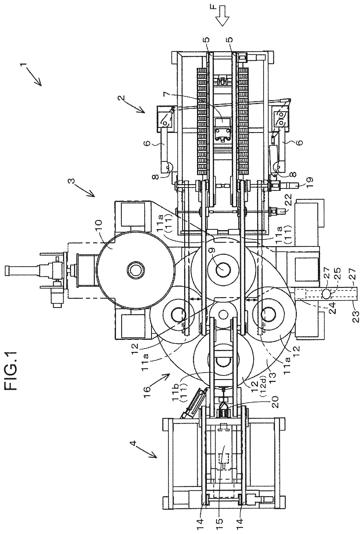
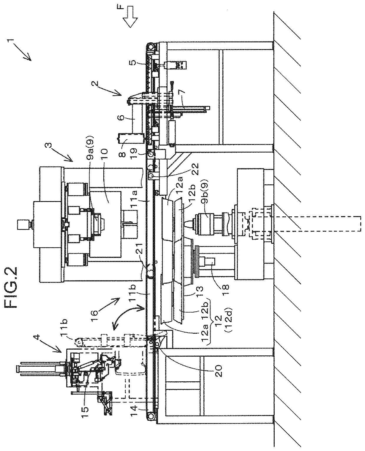
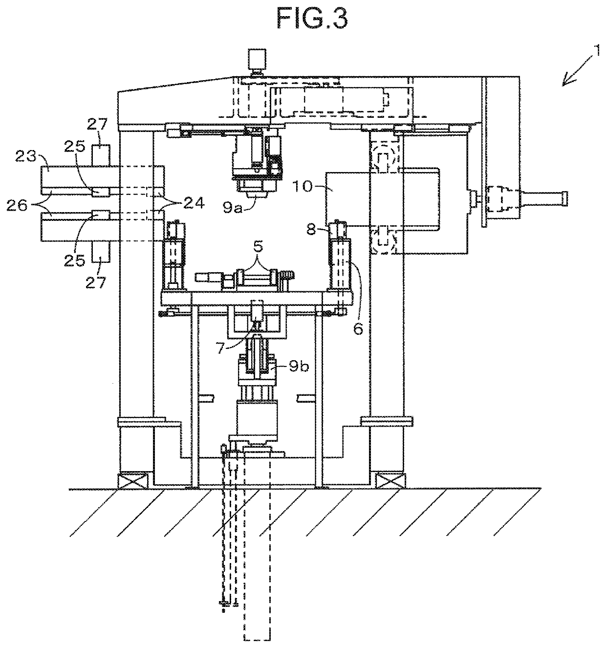
[0017]Below will be described embodiments of the present invention with reference to the drawings. The embodiments described below are examples of embodying the present invention, and the present invention is not limited to the examples.

[0018]FIGS. 1 to 6 show a tire testing machine 1 according to the embodiment. In the below description about the tire testing machine 1, the length of a conveying path F of a tire T in the conveying direction of the tire T corresponds to the total length of the tire testing machine 1. The horizontal direction that intersects with the conveying path F, more accurately the horizontal direction substantially perpendicular to the conveying path F, corresponds to the depth direction of the tire testing machine 1. The depth direction is also referred to as a left-right direction or width direction of the tire testing machine 1.

[0019]The tire testing machine 1 includes a lubrication section 2, a tire testing section 3, and a marking section 4. The lubricati...


PUM


Abstract

Provided is a tire testing machine allowing rim replacement work to be performed easily and safely without requiring a large overall device length. The tire testing machine includes: a rim table allowing a plurality of rims to be placed thereon; a pair of left and right conveyors that convey a tire having been subjected to a tire test and removed from a rim downstream; and a rim replacement mechanism allowing a replacement target rim selected from the rims placed on the rim table to be replaced with another rim. The rim table is rotatable about a vertical axis at a position below the pair of conveyors, and the rims are placed at respective positions arranged in the rotation circumferential direction thereof. The rim replacing mechanism includes a rotational drive mechanism that rotates the rim table to move the replacement target rim to a replacement position.

Description

TECHNICAL FIELD[0001]The present invention relates to a tire testing machine having a function of replacing rims.BACKGROUND ART[0002]Conventionally is known a tire testing machine capable of testing a plurality of tires having different inner diameters or tread surface widths. Specifically, there is known a tire testing machine including a table on which a plurality of rims corresponding to a plurality of tire sizes, respectively, are placed, a spindle on which each of the plurality of rims is removably mounted, and a mounting-removing mechanism for mounting and removing the plurality of rims on and from the spindle, the tire testing machine having a function of semi-automatically or automatically replacing the rims.[0003]However, the tire testing machine has a limited size, not allowing a large number of rims corresponding to the tires of all sizes to be installed on the tire testing machine itself. A typical tire testing machine allows about 4 to 6 rims to be installed thereon. Th...

Claims


Application Information

Patent Timeline
IPC IPC(8): G01M17/02
CPCG01M17/021B60C19/00G01M17/02
Inventor SUMITANI, TAKASHISUMIMOTO, YU
Owner KOBE STEEL LTD
Learn More