Method of forming NiP nonmagnetic film and method of manufacturing magnetic head using the film

A non-magnetic film and magnetic film technology, applied in the application of magnetic film to substrate, magnetic head using thin film, magnetic recording head, etc., can solve the problem of reduced reliability of magnetic head, and achieve high accuracy and high reliability.

Inactive Publication Date: 2008-10-29
FUJITSU LTD
View PDF9 Cites 0 Cited by
  • Summary
  • Abstract
  • Description
  • Claims
  • Application Information

AI Technical Summary

Problems solved by technology

Therefore, the reliability of the conventional magnetic head must be reduced

Method used


Image

  • Method of forming NiP nonmagnetic film and method of manufacturing magnetic head using the film
  • Method of forming NiP nonmagnetic film and method of manufacturing magnetic head using the film
  • Method of forming NiP nonmagnetic film and method of manufacturing magnetic head using the film

Examples


Embodiment Construction

[0027] Preferred embodiments of the present invention will now be described in detail with reference to the accompanying drawings.

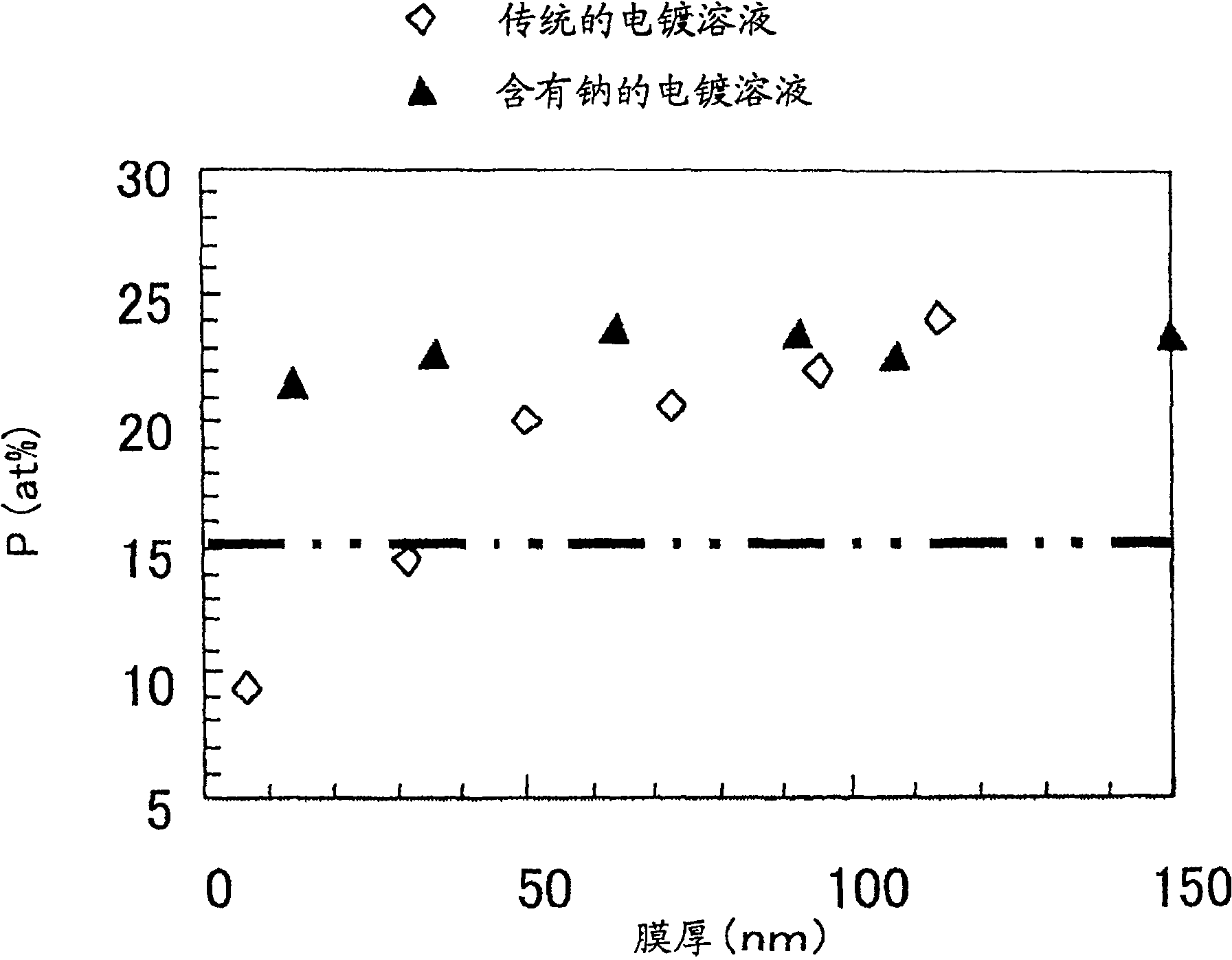
[0028] The following table lists examples of the composition of the NiP plating solution for forming the NiP nonmagnetic film by electrolytic plating. The NiP plating solution contains: nickel sulfate and nickel chloride as reagents for providing nickel (Ni); and phosphoric acid and sodium hydrogenphosphite as reagents for providing phosphorus (P). In addition, sodium citrate providing carboxylate was added to the NiP plating solution.

[0029] It should be noted that the carboxylate-donating reagents that can be added are not limited to sodium citrate. Other reagents that donate carboxylate groups can also be used, but sodium tartrate, which tends to form insoluble precipitates with Ni, cannot be used.

[0030] surface

[0031] Reagent

Concentration ratio (Mol / l)

nickel sulfate

0.095~0.19

nickel chloride

...


PUM

PropertyMeasurementUnit
thicknessaaaaaaaaaa

Abstract

The method is capable of easily and securely forming a NiP nonmagnetic film. In the method of forming the NiP nonmagnetic film by electrolytic plating, the electrolytic plating is performed in NiP plating solution consisting of: a reagent for supplying nickel ions; a reagent for supplying phosphorus ions; and a reagent including carboxyl groups. For example, sulfates and chloride salts of nickel, etc. may be use as the reagent for supplying nickel ions; phosphorus acid, sodium phosphite, etc. may be used as the reagent for supplying phosphorus ions.

Description

technical field [0001] The present invention relates to a method for forming a NiP nonmagnetic film and a method for manufacturing a magnetic head using the NiP nonmagnetic film, in particular to a method for forming a NiP nonmagnetic film by electrolytic plating and a method for manufacturing a magnetic head using the NiP nonmagnetic film. Background technique [0002] Figure 6 is a cross-sectional view showing a stacked structure of a read head and a write head of a magnetic head, Figure 7 It is an explanatory diagram of a read head and a write head viewed from the air-loaded surface of the magnetic head. The magnetic head 10 has a read head 20 and a write head 30 stacked on a substrate. The read head 20 is constituted by forming the MR element 23 between the lower shield layer 21 and the upper shield layer 22 . In the write head 30, a write gap layer 33 is formed between the upper shield layer 22 and the upper magnetic pole 32, and the upper shield layer 22 is general...

Claims


Application Information

Patent Timeline
Patent Type & Authority Patents(China)
IPC IPC(8): G11B5/31H01F41/14
CPCG11B5/232C25D3/562G11B5/3163G11B5/235B65G67/46
Inventor 三宅裕子加藤雅也
Owner FUJITSU LTD
Why Eureka
Try Eureka