Eureka AIR delivers breakthrough ideas for toughest innovation challenges, trusted by R&D personnel around the world.

System and method for de-plugging rotating ground engaging tools of an agricultural implement

Active Publication Date: 2021-02-18
CNH IND CANADA
View PDF0 Cites 1 Cited by
  • Summary
  • Abstract
  • Description
  • Claims
  • Application Information

AI Technical Summary

Benefits of technology

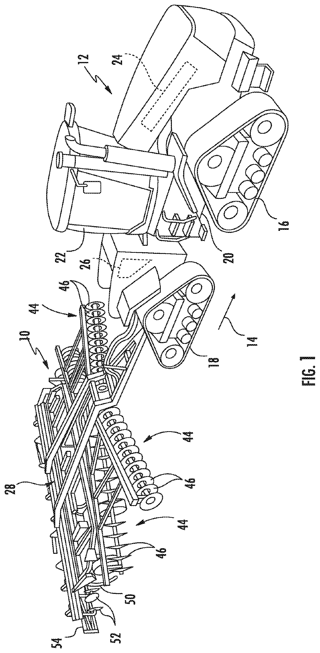
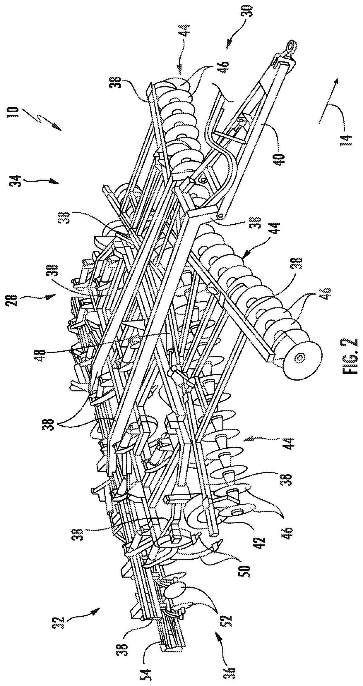
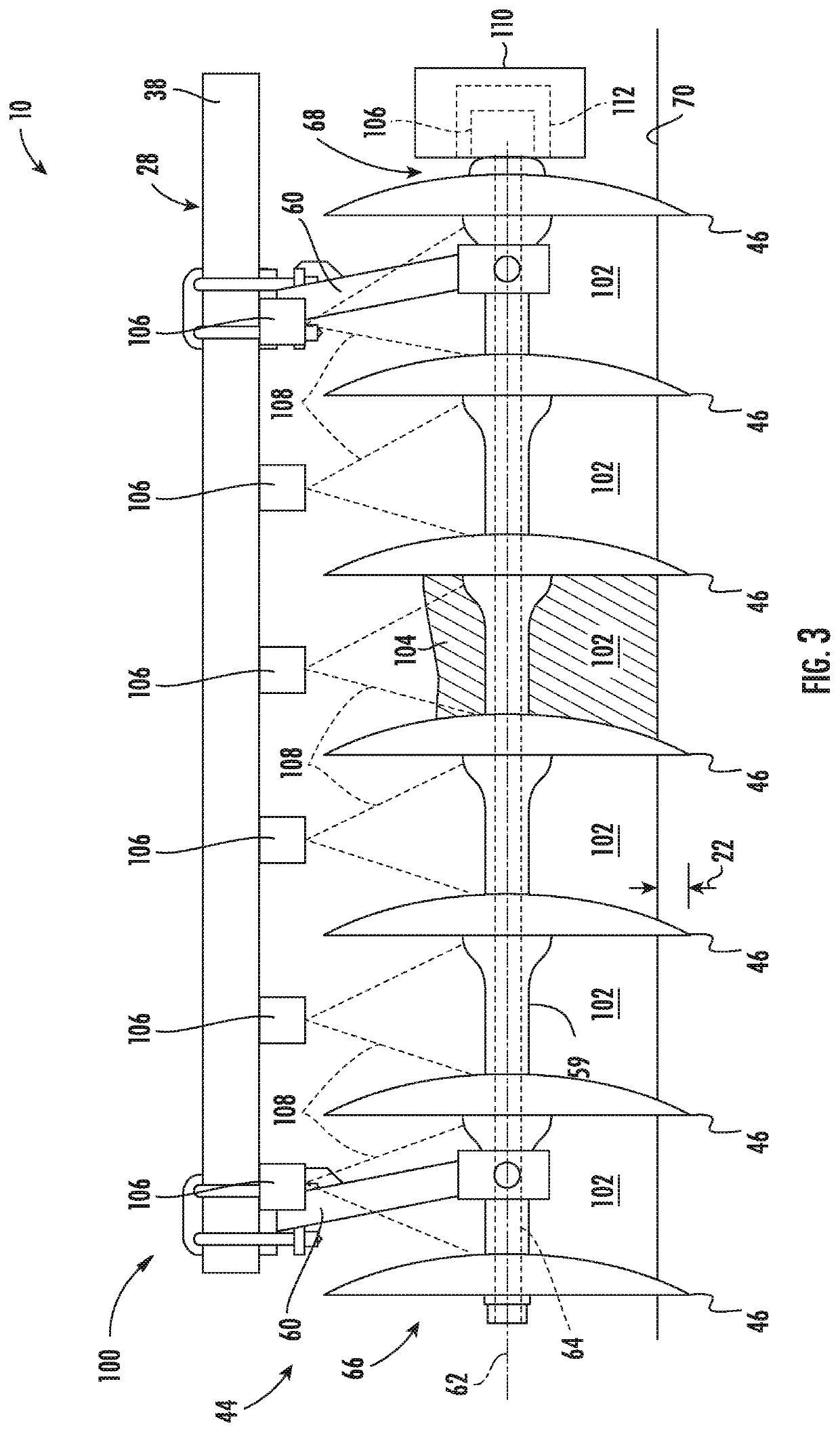
[0006]In one aspect, the present subject matter is directed to a system for de-plugging rotating ground engaging tools of an agricultural implement. The system includes first and second ground engaging tools configured to be supported relative to a frame of an agricultural implement, with the first and second ground engaging tools being spaced apart from each other such that a flow gap is defined between the tools. The system also includes a rotational actuator configured to rotationally drive the first and second ground engaging tools about a rotational axis, a sensor configured to capture data indicative of material accumulation within the flow gap defined between the first and second ground engaging tools, and a controller communicatively coupled to the rotational actuator and the sensor. The controller is configured to determine when the first and second ground engaging tools are experiencing a plugged condition based on the data received from the sensor. Additionally, in response to the determination that the first and second ground engaging tools are experiencing the plugged condition, the controller is further configured to control an operation of the rotational actuator such that the tools are rotationally driven about the rotational axis while such tools are disposed at a wo

Problems solved by technology

During tillage operations, field materials, such as residue, soil, rocks, and/or the like, may become trapped or otherwise accumulate between adjacent rotating ground engaging tools of the implement.
Such accumulation of field materials may inhibit the operation of the rotating ground engaging tools in a manner that prevents the tools from providing adequate tillage to the field.
For instance, ma

Method used


Image

  • System and method for de-plugging rotating ground engaging tools of an agricultural implement
  • System and method for de-plugging rotating ground engaging tools of an agricultural implement
  • System and method for de-plugging rotating ground engaging tools of an agricultural implement

Examples


Example

[0016]Repeat use of reference characters in the present specification and drawings is intended to represent the same or analogous features or elements of the present technology.

DETAILED DESCRIPTION OF THE DRAWINGS

[0017]Reference now will be made in detail to embodiments of the invention, one or more examples of which are illustrated in the drawings. Each example is provided by way of explanation of the invention, not limitation of the invention. In fact, it will be apparent to those skilled in the art that various modifications and variations can be made in the present invention without departing from the scope or spirit of the invention. For instance, features illustrated or described as part of one embodiment can be used with another embodiment to yield a still further embodiment. Thus, it is intended that the present invention covers such modifications and variations as come within the scope of the appended claims and their equivalents.

[0018]In general, the present subject matter...


PUM


Abstract

A system for de-plugging rotating ground engaging tools of an agricultural implement includes first and second ground engaging tools spaced apart from each other such that a flow gap is defined between the tools, a rotational actuator configured to rotationally drive the tools about a rotational axis, a sensor configured to capture data indicative of material accumulation within the flow gap defined between the tools, and a controller configured to determine when the tools are experiencing a plugged condition based on the data received from the sensor. Additionally, in response to the determination that the tools are experiencing the plugged condition, the controller is further configured to control an operation of the rotational actuator such that the tools are rotationally driven while such tools are disposed at a working position relative to a soil surface of a field.

Description

FIELD OF THE INVENTION[0001]The present disclosure generally relates to agricultural implements and, more particularly, to systems and methods for de-plugging rotating ground engaging tools of an agricultural implement by rotationally driving such tools when material accumulation is detected.BACKGROUND OF THE INVENTION[0002]It is well known that, to attain the best agricultural performance from a field, a farmer must cultivate the soil, typically through a tillage operation. Modern farmers perform tillage operations by pulling a tillage implement behind an agricultural work vehicle, such as a tractor. Tillage implements typically include one or more ground engaging components configured to rotate relative to the soil as the implement is moved across the field. For example, in certain configurations, the implement may include one or more harrow disks, leveling disks, rolling baskets, and / or the like. Such rotating ground engaging component(s) loosen and / or otherwise agitate the soil ...

Claims


Application Information

Patent Timeline
IPC IPC(8): A01B33/16A01B9/00
CPCA01B33/16A01B33/024A01B9/003A01B15/16A01B33/12A01B71/08A01B79/005
Inventor HENRY, JAMES W.
Owner CNH IND CANADA
Why Eureka
Eureka Blog
Learn More