Networked diagnostic and control system for dispensing apparatus

a networked diagnostic and control system technology, applied in the direction of ratio control, special dispensing means, special data processing applications, etc., can solve the problems of increasing the cost of agrochemicals and inadvertent spray drift or pesticide run-off, application errors that are significant yet unavoidable,

Active Publication Date: 2006-11-23
CAPSTAN
View PDF14 Cites 95 Cited by
  • Summary
  • Abstract
  • Description
  • Claims
  • Application Information

AI Technical Summary

Benefits of technology

[0031] In a further aspect of the invention, the relationship between the physical location of the nozzle mode on the spray boom and the electronic address must be known in order to control or monitor individual nozzles based on their location. Thus, the vibration sensor is used to sense the impact of a “rap” or sharp impact on the nozzle to set up the nozzle locations on the spray boom. A visual indicator (e.g. an LED) can be used to show the operator when the rap on the nozzle is successful to claim the boom location on the control area network bus system. Further, the visual indicator will help the operator locate a particular nozzle when a problem is indicated on the operator interface. Thus, the operator will not have to remember a number displayed on the operator interface associated with a particular nozzle when he turns off the spray and exits the cab to look for the nozzle. Since the nozzle is not spraying, the operator can simply look for the LED to indicate the problematic nozzle.

Problems solved by technology

Agrochemical manufacturers and regulatory officials are becoming increasingly interested in the spray application process since it affects product efficacy and environmental contamination.
There are increasing concerns over inefficient agrochemical use, the cost of agrochemicals and inadvertent spray drift or pesticide run-off.
Faster ground speeds and wider spray booms can lead to application errors that are significant yet unavoidable with existing spray technology.
Unless the flow rate from each nozzle is individually adjusted to compensate for these differences in travel speeds, application errors may occur.
Currently, the maximum resolution (smallest area that can get a distinct rate) for most products is limited by the width of the spray boom.
Rate controllers usually control the entire boom as a unit and do not allow different boom sections, let alone individual nozzles, to discharge different rates.
Some increase in spatial resolution of variable rate application can be achieved by individual control of distinct boom sections using existing technology but the systems can involve cumbersome plumbing, wiring and operator interfaces.
Since the operator is unlikely to stop the vehicle and leave the cab between refillings, clogged nozzles or other problems on the boom are unlikely to be detected while significant land areas are being treated.
Additionally, the wider boom widths, travel speeds and vehicle sizes increasingly restrict an operator's view of the boom and the opportunities to view the boom while driving.
A similar problem exists on shielded or shrouded sprayers sometimes used in the North American Plains and in urban and landscape applications.
In farming areas in extreme southern and northern latitudes and in high value specialty crops, often grown in coastal areas, the agronomic time window for pesticide applications can be critically short and often occurs during windy periods.
Improperly operating nozzles are not easily detected.
While effective, this requires cumbersome plumbing for each nozzle, and the operator must visually monitor the bank of tubes.
Relying on visual inspection (either direct line of sight or video) or simple flow measurement (ball-in-tube) does not assure proper nozzle operation.
Nozzles can be partially clogged or have an obstruction in the flow path and appear to be operating correctly even if the flow rate is significantly affected.
Conversely, the nozzle pattern and spray droplet size can be severely distorted by an obstruction or damage, yet the flow rate remains close to the original value.
In this regard, the ball-in-tube monitors are not sensitive enough to detect clogs that could be sufficiently severe enough to require re-treatment of the spray area.
Even with the electronic control or monitor system, the driver would likely remain unaware of the failure.
The opportunity for failure is increased over that of a simple nozzle.
For example, on irrigation systems, there may be many small nozzles, often obscured from view or in areas that are difficult to access.
Failure of a nozzle might not be detected until drought damage to a plant had occurred and symptoms were visible.
Likewise, in industrial spray driers, malfunction of a nozzle might not be detected until significant amounts of product have been damaged.
In spray humidification or cooling systems, nozzle failures might not be detected until excessive heating or drying had occurred.

Method used


Image

  • Networked diagnostic and control system for dispensing apparatus
  • Networked diagnostic and control system for dispensing apparatus
  • Networked diagnostic and control system for dispensing apparatus

Examples


example no.1

EXAMPLE NO. 1

[0102] Characteristic vibration of the spray atomization process was investigated using a single nozzle test stand, a multiple nozzle test stand and a commercial, self-propelled field sprayer (Case 4260, CNH Global). The single nozzle test stand used air-pressured canisters for liquid flow; this eliminated any vibration from pumps and bypass flow in the system. The multiple (3) nozzle test stand used an electric vane pump and allowed various configurations of pulsing flow to be generated. Data from the multiple (3) nozzle test stand were compared to the single nozzle stand. Pump and pipe flow vibrations were not found to affect the nozzle vibration measurements. Detailed results of the testing are provided in the report, “Sensing Spray Nozzle Vibration as a Means for Monitoring Operation,” by D. K. Giles, presented at ILASS Americas, 17th Annual Conference on Liquid Atomization and Spray Systems, Arlington, Va., May 2004.

[0103] The primary instrument for data collectio...

example no.2

EXAMPLE NO. 2

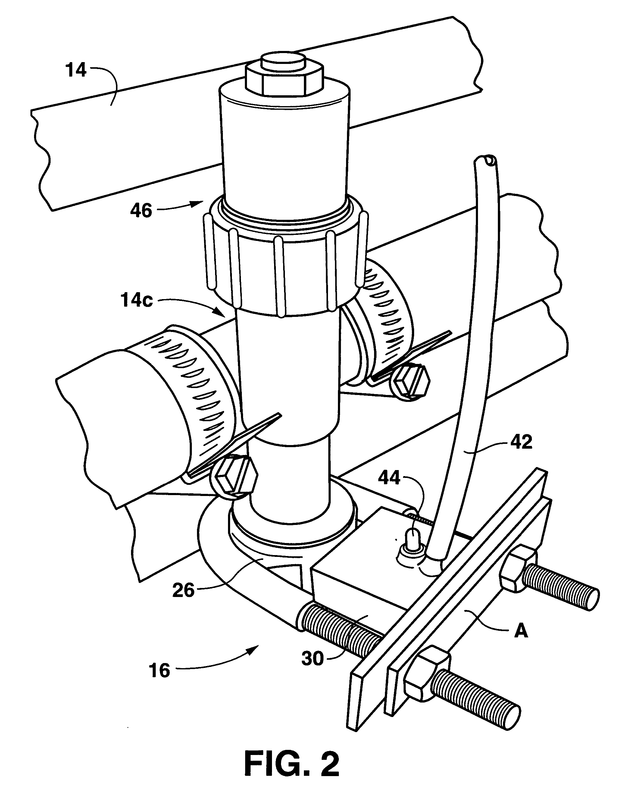
[0116] The nozzle control and monitor system depicted in FIGS. 2, 3 and 4 was installed on a self-propelled sprayer and operated while spraying a fallow field. The spray boom was outfitted with the system components and tested with flat fan agricultural spray nozzles. For the tests reported here, the nozzle used was a 110-degree nozzle with a flow rate of 0.6 gpm when operated at 40-psi liquid pressure. During the operation, the Fourier transformed vibration was recorded from each sensor at approximately one-second intervals; the average vibration and the standard deviation of the vibration value was calculated for all the nozzles. Vibration was linearly scaled to arbitrary units.

[0117] A number of typical conditions were tested and the results are shown in FIG. 7A for the specific conditions described in FIG. 7B. The test numbers in the horizontal axis of FIG. 7A correspond to the test numbers in the leftmost column of FIG. 7B. Performance of the system can be evaluat...

example no.3

EXAMPLE NO. 3

[0121] In addition to monitoring the proper operation of spray nozzles in a spraying system, the technique can be used to monitor the proper operation of other flow components, such as filters and pumps. While the monitoring of rotational components such as bearings, fans and the like by vibration is a technique well known in the art, the use of vibration as a means to detect partial clogging of a liquid system filter is an integral and new capability for the networked spray monitor.

[0122] The technique was investigated as a clogged filter detector. An accelerometer was coupled to the base of a common agricultural spray filter housing (1″ Arag filter housing). Clogged filter elements were then created by coating a portion of the filter element with epoxy glue to create an impassible flow path. The filter was supplied with pressurized water at 60 psi and the resulting vibration for each condition (0%, 50%, 75% and 100% clogged filters) was recorded. The resulting data i...


PUM


Abstract

A networked delivery system and method for controlling operation of a spraying system includes nozzles for emitting an agrochemical according to a predetermined spray pattern and flow rate; vibration sensors located adjacent an agricultural spray system component to sense vibrations of the agricultural spray system component, such as spray nozzles. The networked delivery system also includes a control area network with a computer processor in communication with the vibration sensors. The processor conveys information to an operator regarding the agricultural spray system component based on the sensed vibrations. The processor also actuates each of the agricultural spray system components such as the spray nozzles to selectively control each of the nozzles or a designated group of the nozzles.

Description

BACKGROUND OF THE INVENTION [0001] Most agrochemicals such as crop protection agents and many fertilizers are applied as liquid solutions, suspensions and emulsions that are sprayed onto target fields. Conventional spray technology is well known and generally understood by farmers, equipment manufacturers and extension agents. Agrochemical manufacturers and regulatory officials are becoming increasingly interested in the spray application process since it affects product efficacy and environmental contamination. [0002] Typically, the agrochemical liquid is supplied by powered pumps to simple or complex orifice nozzles that atomize the liquid stream into spray droplets. Nozzles are often selected primarily on the desired range of flow rates needed for the job and secondarily on the range of liquid droplet size spectra and spray distribution patterns they produce. Nozzle technology has been an area of significant development work in recent years. The number of manufacturers of nozzles...

Claims


Application Information

Patent Timeline
Patent Type & Authority Applications(United States)
IPC IPC(8): G05D11/00B67D7/08
CPCA01B79/005A01C23/007B05B15/02B05B12/082B05B12/004B05B15/50Y10T137/1866
Inventor GILES, DURHAM KENIMERNEEDHAM, DUANE
Owner CAPSTAN
Why Eureka
Try Eureka