
Input/output system

a technology of input/output system and input/output, which is applied in the direction of program control, instrumentation, support structure mounting, etc., can solve the problems of 1, 2a, 2b not providing a truly fault-tolerant system, and achieve the effect of system functionality being restored and restoring the other way

Active Publication Date: 2021-04-01
ROCKWELL AUTOMATION TECH
View PDF7 Cites 3 Cited by
  • Summary
  • Abstract
  • Description
  • Claims
  • Application Information

AI Technical Summary

Benefits of technology

The patent text identifies a need for an input / output system that can avoid single-point failure, which results in downtime or system disruption. The system should be responsible for continuous and uninterrupted operation of certain processes or systems, such as in industrial automation. It should also allow for easy repair and configuration of redundant components.

Problems solved by technology

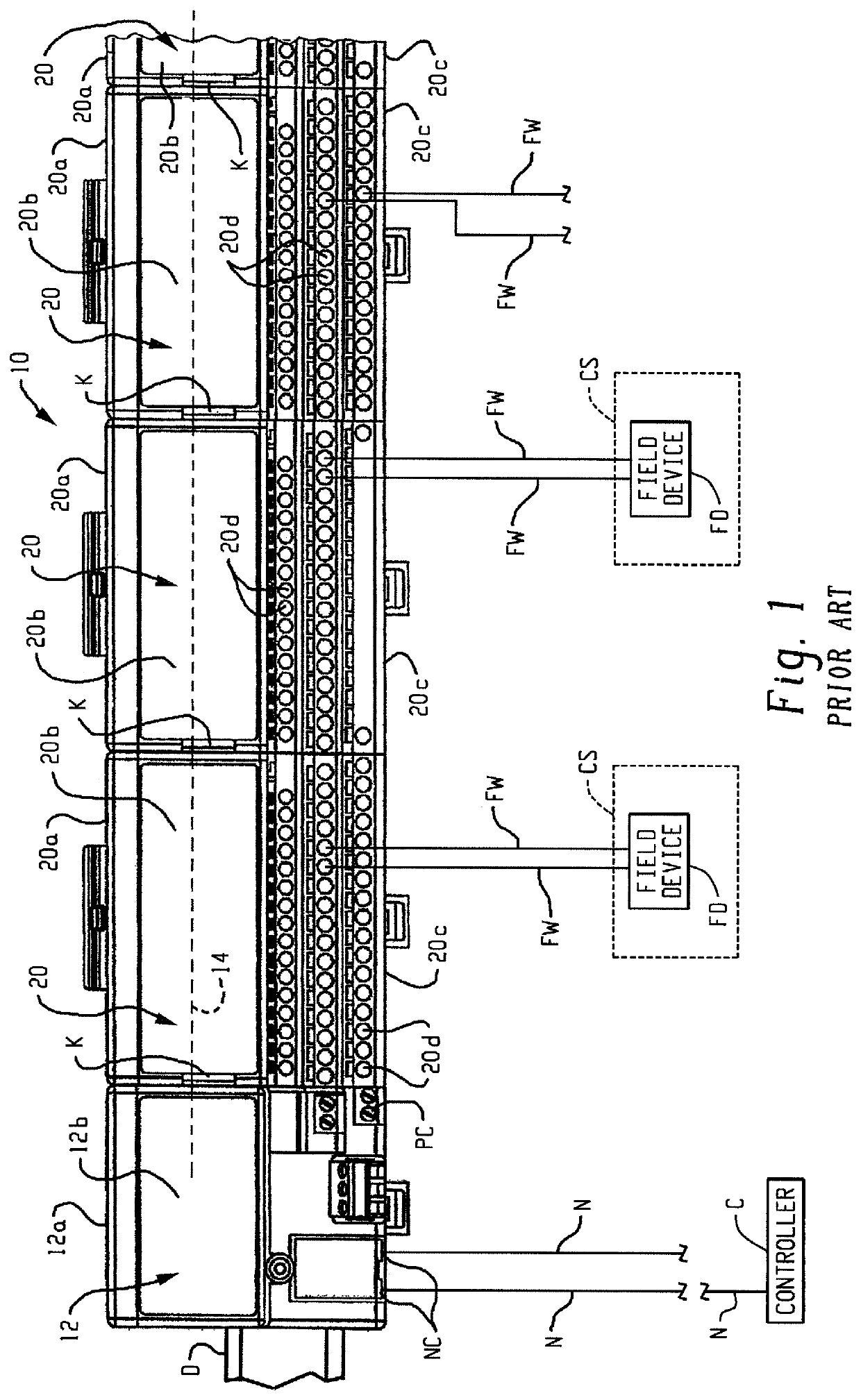
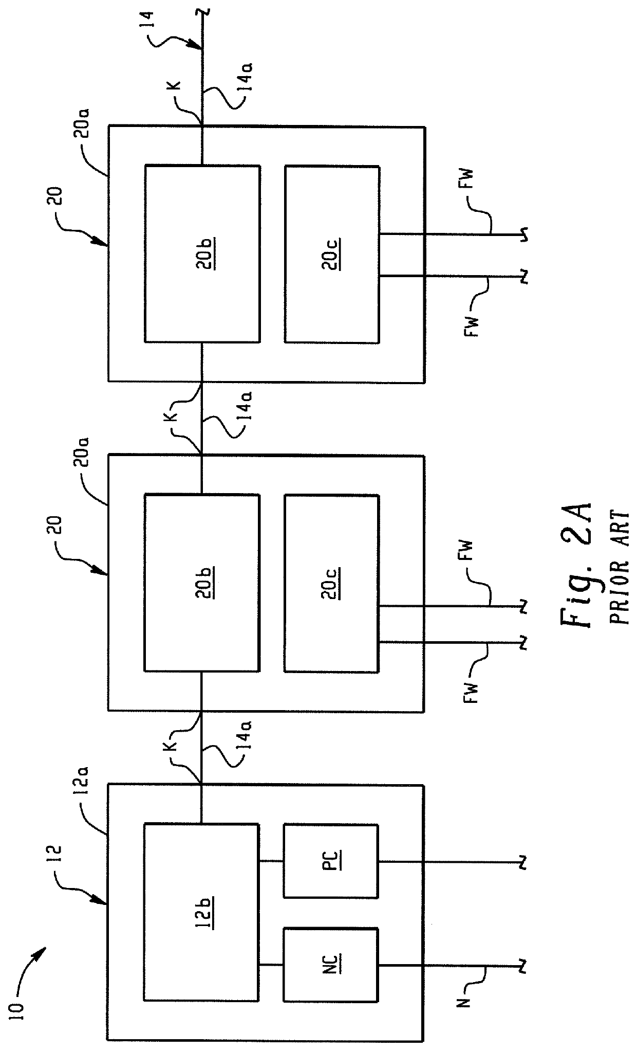
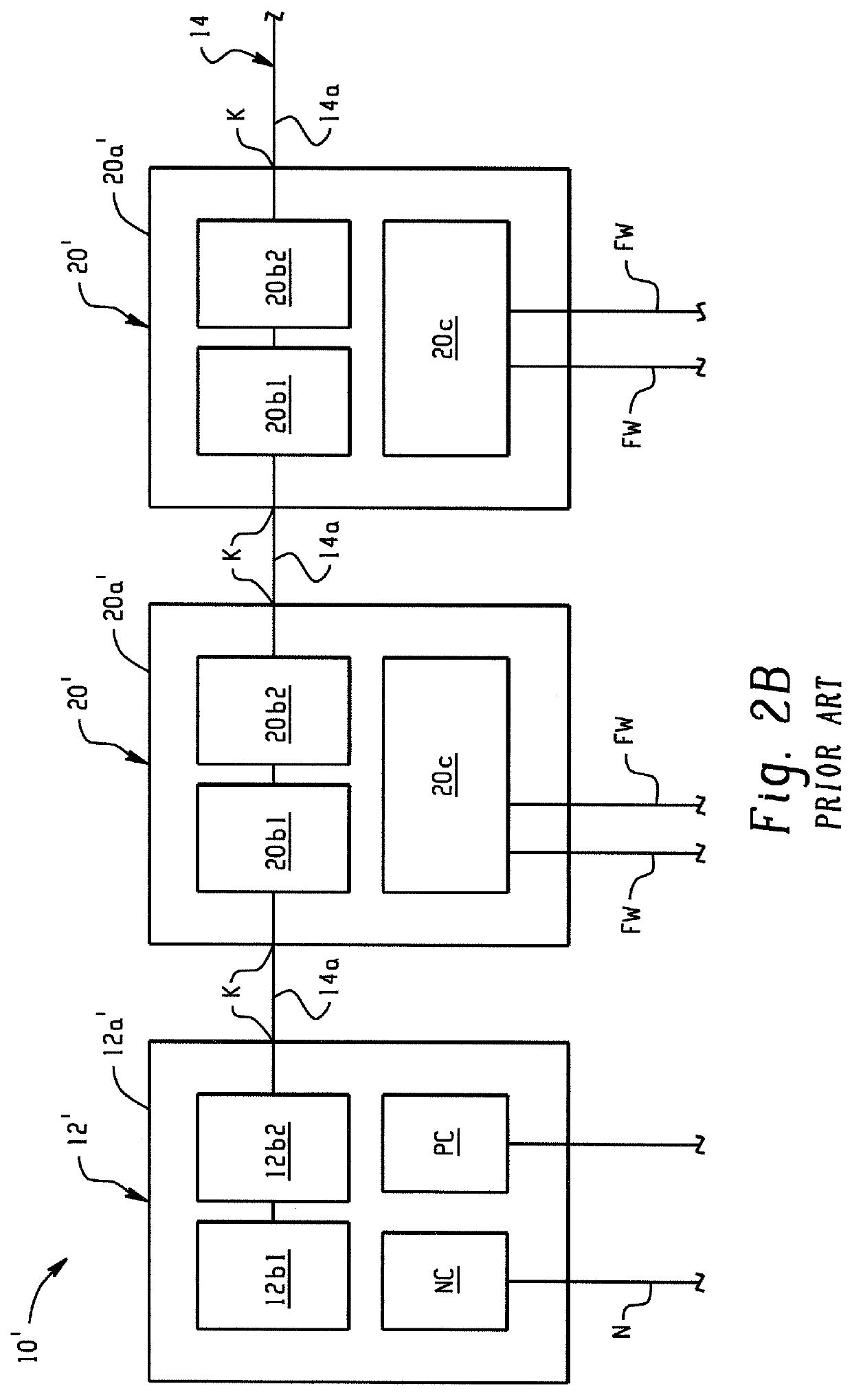
The systems of FIGS. 1, 2A, 2B do not provide a truly fault tolerant system in that the certain components are not redundant.

Method used


Image

  • Input/output system
  • Input/output system
  • Input/output system

Examples


Embodiment Construction

[0023]FIG. 3 shows a distributed modular I / O system 110 in accordance with an embodiment of the present development. As described in detail below, the system 110 comprises redundant backplane 114 for improved fault tolerance. In one example, the backplane 114 comprises first and second redundant ethernet networks 114a,114b implementing a suitable Ethernet data communications protocol such as a gigabit speed protocol but any other network and / or communications protocol can be implemented without departing from the scope and intent of the present development.

[0024]The distributed modular I / O system 110 includes a network adapter 112 that is operatively connected to at least one industrial automation network N1,N2. As shown herein, the network adapter is connected to first and second redundant industrial automation networks N1,N2 such as first and second Parallel Redundancy Protocol (PRP) LAN networks or the like such as Ethernet / IP networks or other industrial automation networks so t...


PUM


Abstract

An I / O system having redundant removable and / or replaceable components. Each of the removable / replaceable components can be removed by displacement parallel to a common axis. An I / O device having an I / O base with a lock-out toggle to prevent installation of one or more I / O modules to the I / O base unless a ground screw has been secured to supporting structure.

Description

FIELD[0001]The present development relates to industrial automation control systems and, more particularly, to a modular input / output (I / O) system.BACKGROUND INFORMATION[0002]Distributed modular input / output (I / O) systems for industrial automation control systems are well-known and in widespread use. Referring to FIG. 1, a known distributed modular I / O system 10 includes a network adapter 12 that is operatively connected to an industrial automation network N such as an Ethernet / IP network or other industrial automation network so that the network adapter 12 receives data from, transmits data to, and otherwise communicates with an industrial control module or “controller” C also connected to the network N. The controller C comprises one or more programmable logic controllers (PLC), microprocessors, and / or other electronic processors.[0003]The adapter 12 includes an adapter base 12a that is mounted to a DIN rail D or other support structure, and an adapter module 12b is permanently or...

Claims


Application Information

Patent Timeline
Patent Type & Authority Applications(United States)
IPC IPC(8): H05K7/14
CPCH05K7/1465H05K7/1468H05K7/1477H05K7/1484H05K7/1474G05B2219/1105G05B2219/14014G05B2219/15078H05K7/1478
Inventor WROBEL, ADAM M.LOSTOSKI, DOUG A.ESTANEK, BRIAN T.KILLIAN, DANIEL E.
Owner ROCKWELL AUTOMATION TECH
Learn More