Time-of-flight imaging apparatus and time-of-flight imaging method

Pending Publication Date: 2021-06-03
SONY SEMICON SOLUTIONS CORP
View PDF5 Cites 0 Cited by
  • Summary
  • Abstract
  • Description
  • Claims
  • Application Information

AI Technical Summary

Problems solved by technology

However, as it is generally known, when a signal, such as the above-mentioned correlation wave, is sampled at less than the double of the highest frequency of the correlation wave, a frequency aliasing may occ

Method used


Image

  • Time-of-flight imaging apparatus and time-of-flight imaging method
  • Time-of-flight imaging apparatus and time-of-flight imaging method
  • Time-of-flight imaging apparatus and time-of-flight imaging method

Examples


Embodiment Construction

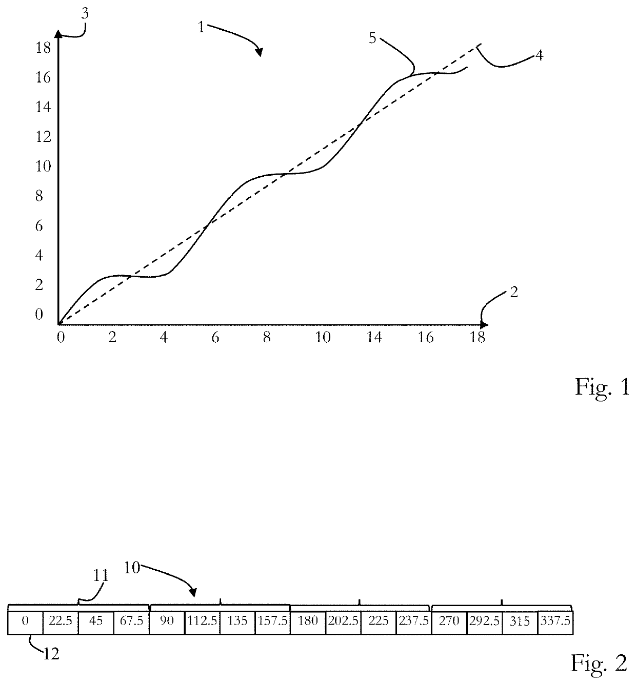
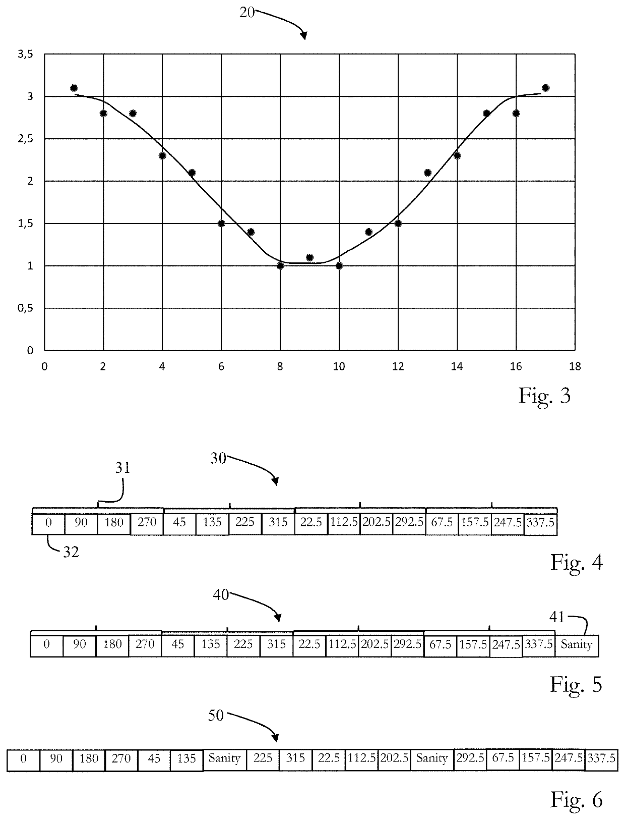
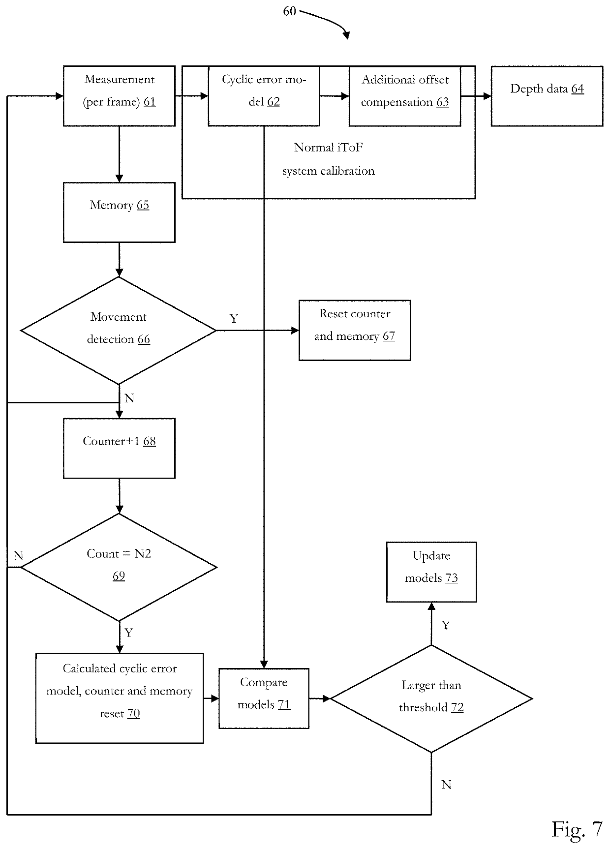
[0021]Before a detailed description of the embodiments under reference of FIG. 7, general explanations are made.

[0022]As mentioned in the outset, known calibrations of ToF systems, such as of indirect ToF devices, systems or cameras may performed during or at the end of a manufacturing process for determining a cyclic error.

[0023]But, there are factors, such as temperature, aging of the hardware and a different voltage supply, which may deteriorate the cyclic error after the manufacturing and therefore the calibration may deteriorate, as well.

[0024]Furthermore, it has been recognized that an initial manufacturing calibration done by the manufacturer may not compensate an interference of motion of the ToF device or a motion of the to be imaged scene (e.g. an object) during a normal operation of the ToF device, which may cause a reduced signal to noise ratio (compared to the normal operation).

[0025]Hence, the error of the measured depth information may not be compensated for, since th...


PUM


Abstract

The present disclosure generally pertains to a time-of-flight imaging apparatus having circuitry configured to: demodulate, in a normal operation mode for determining a distance to a scene, at a predetermined number of phase locations a modulated light sensing signal representing modulated light reflected from the scene, thereby generating imaging frames for determining the distance to the scene, and apply, during the normal operation mode, a phase sweep by shifting the predetermined number of phase locations, thereby generating phase sweep frames for determining a cyclic error.

Description

CROSS-REFERENCE TO RELATED APPLICATIONS[0001]The present application claims priority to European Patent Application 19180914.4 filed by the European Patent Office on Jun. 18, 2019, the entire contents of which being incorporated herein by reference.TECHNICAL FIELD[0002]The present disclosure generally pertains to a time-of-flight imaging apparatus and a time-of-flight imaging method.TECHNICAL BACKGROUND[0003]Generally, there are different ways of obtaining a depth image with time-of-flight (ToF) technology.[0004]Time-of-flight includes a variety of methods that measure the time that an object, particle or wave needs for traveling a distance in a medium. Known ToF cameras can obtain depth measurements of objects in a scene for every pixel of the depth image simultaneously, wherein the depth image is captured with a ToF camera. For capturing this image, the ToF device or camera typically illuminates the scene with a modulated wave and images the backscattered wave with an image sensor...

Claims


Application Information

Patent Timeline
IPC IPC(8): G06T7/55G01S17/894G01S7/4915G01S7/497
CPCG06T7/55G01S17/894G06T2207/10016G01S7/497G06T2207/10028G01S7/4915G01S17/26
Inventor CHEN, YEVAN DER TEMPEL, WARD
Owner SONY SEMICON SOLUTIONS CORP
Why Eureka
Try Eureka