Vehicle rearview mirror system

a rearview mirror and vehicle technology, applied in the field of vehicle rearview mirror systems, can solve the problems of reducing the driver's ability to discern detail, affecting the driver's perception of detail, and the display is not so bright, and achieve the effect of low cos

Inactive Publication Date: 2005-07-19
DONNELLY CORP
View PDF25 Cites 98 Cited by
  • Summary
  • Abstract
  • Description
  • Claims
  • Application Information

AI Technical Summary

Benefits of technology

[0009]The present invention provides for the utilization of commercially available, low cost, silicon-based light-sensing devices in automatic rearview mirror control systems. The present invention also provides a control for a display through a mirrored surface of a vehicular rearview mirror which is operable to adjust the intensity or brightness of the display in response to the brightness of a scene rearward of the vehicle.
[0013]The various aspects of the present invention utilize common integration elements to measure the light sensors sequentially such that errors due to, for example, component variations are corresponding for both glare and ambient measurements. This facilitates use of mass-produced silicone sensors and avoids the need for matching of components. The various aspects of the invention also achieve sensing of wide input light level dynamic range using off-the-shelf light sensors.
[0018]Therefore, the present invention provides an electrochromic rearview mirror system incorporating a display and a display intensity control which includes an intensity adjustment responsive in at least part of its operating range to the brightness of the rearward scene. The display intensity is adjusted to maintain an appropriate intensity level where it is easily viewable by the driver of the vehicle. The display intensity is bright enough to be seen clearly yet not so bright to annoy or distract the driver. The display intensity is also controlled to provide a sufficient contrast ratio against the variable background brightness of the reflected scene.

Problems solved by technology

In such displays, it is typical to control the display brightness according only to ambient lighting conditions, such that in bright ambient lighting conditions, the display is bright enough to read, but in low ambient lighting conditions, the display is not so bright that it is annoying or distracting to the driver of the vehicle.
For example, a very bright display in dark driving conditions can reduce the driver's ability to discern detail in the forward view, since such a display may cause the driver's pupils to adjust in order to accommodate the bright light source.

Method used


Image

  • Vehicle rearview mirror system
  • Vehicle rearview mirror system
  • Vehicle rearview mirror system

Examples


Embodiment Construction

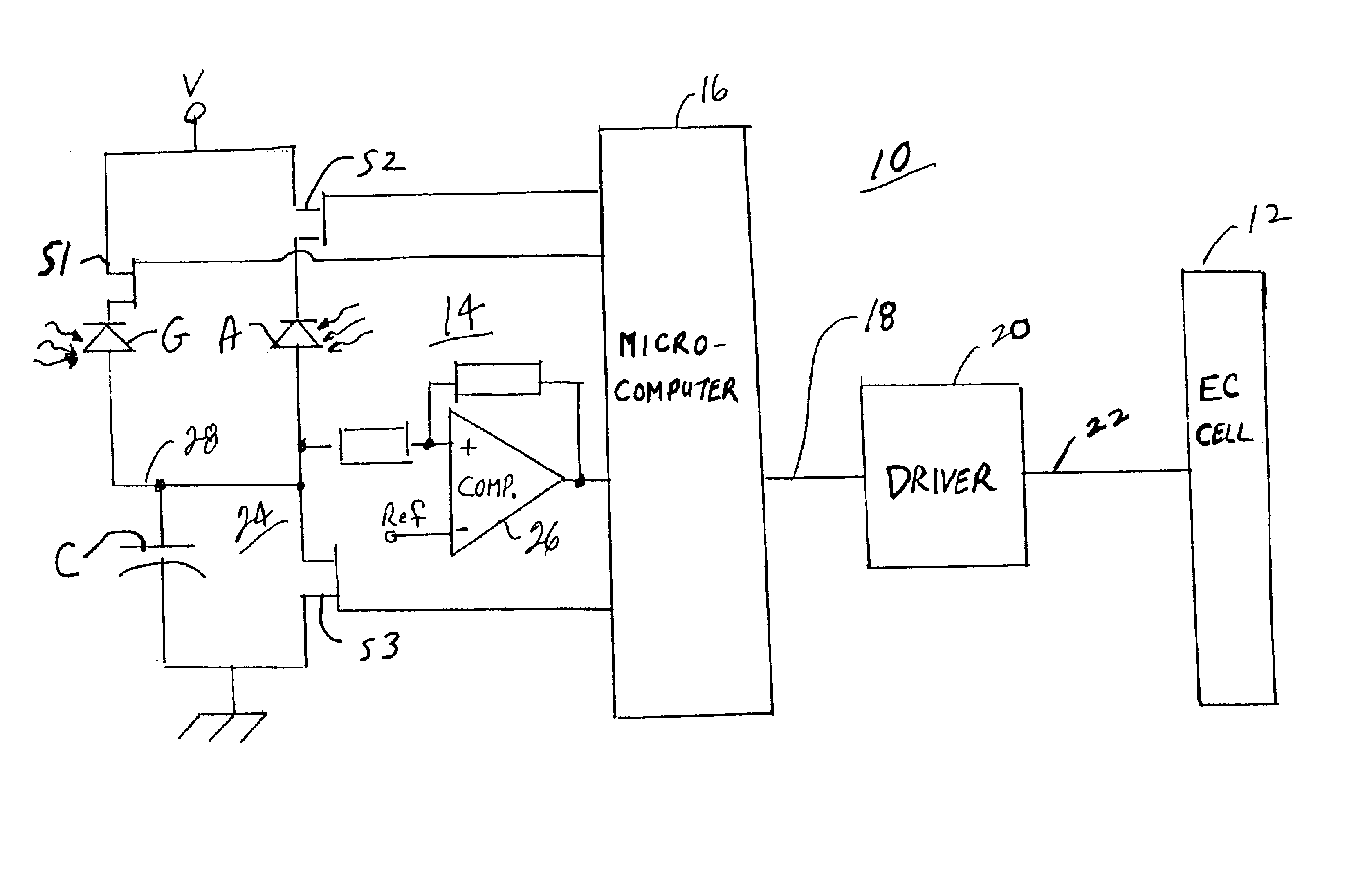
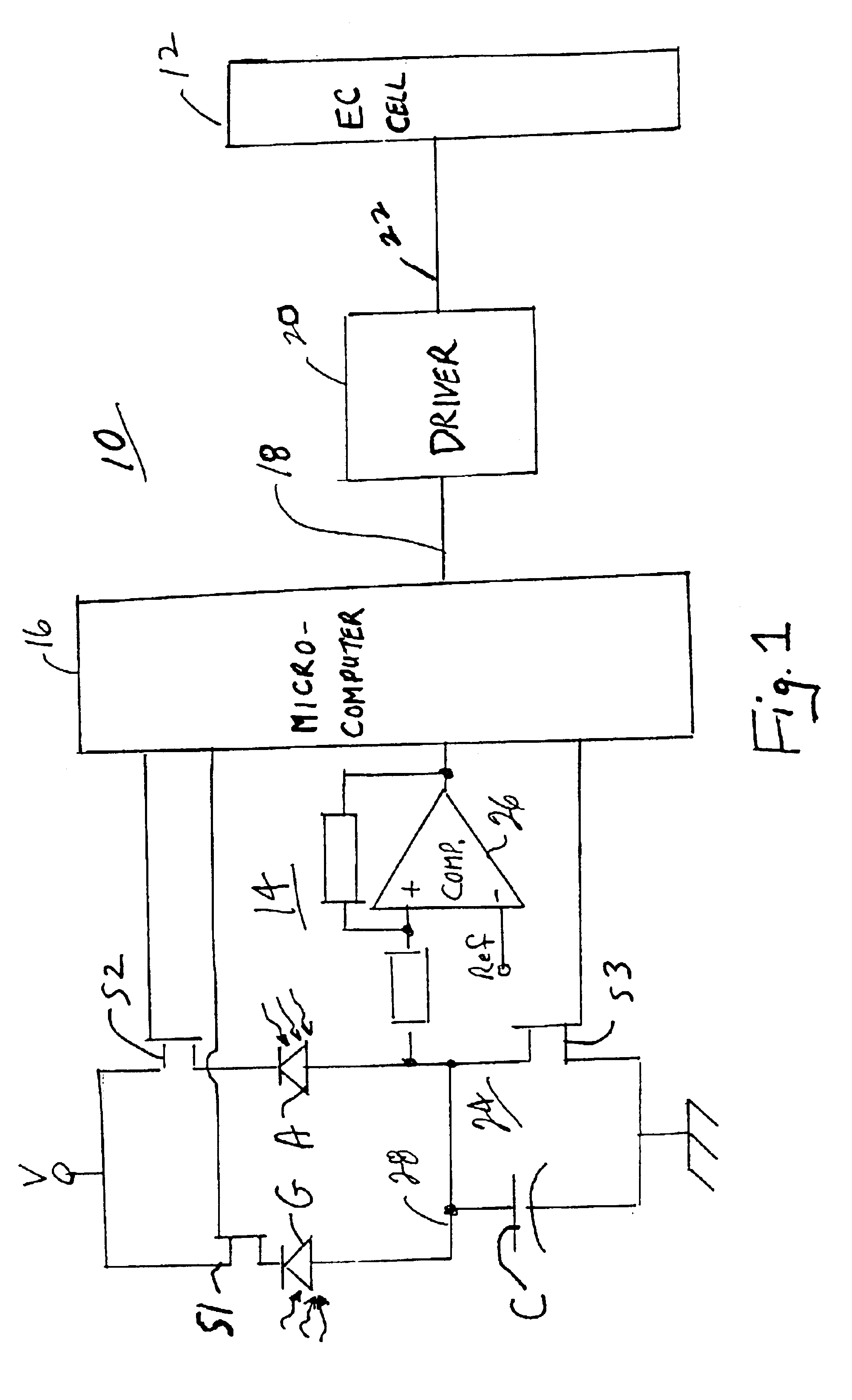
[0029]Referring now specifically to the drawings, and the illustrative embodiments depicted therein, a vehicle rearview mirror system 10 includes an electro-optic reflective element 12, an ambient light sensor A that is operable to sense ambient light, a glare light sensor G that is operable to sense glare-producing light, and a circuit 14 that responds to ambient light sensor A and glare light sensor G and which establishes a reflectance level of reflective element 12 (FIG. 1). Circuit 14 includes a controller 16, which may be defined by a microcontroller, such as a microcomputer, which produces an output 18 indicative of a desired reflectance level of reflective element 12, and a driver 20 which produces an output signal at 22 which establishes the reflectance level of reflective element 12. Driver 20 may be of various configurations. One such configuration includes a switching device which is operable by controller 16 at a particular duty cycle to establish the reflectance level ...


PUM


Abstract

A vehicle rearview mirror system includes an electro-optic reflective element, an ambient light sensor that is operable to sense ambient light, a glare light sensor that is operable to sense glare light and a circuit that is responsive to the ambient glare light sensors which establishes a reflectance level of the reflective element. The circuit includes a sensor-responsive device and a controller. The sensor-responsive device produces an output that is a function of light sensed by glare and ambient light sensors. The controller connects one of the glare and ambient light sensors at a time with the sensor-responsive device to establish glare and ambient light levels and thereby the reflectance level of the reflective element. The mirror system may include a display operable to project light through the reflective element and may control the intensity of the display as a function of the glare light and ambient light.

Description

CROSS REFERENCE TO RELATED APPLICATIONS[0001]The present application claims priority of U.S. provisional applications, Ser. No. 60 / 377,561, filed May 3, 2002 by Schofield for CONTROL OF DISPLAY THROUGH MIRRORED SURFACE; and Ser. No. 60 / 426,227, filed Nov. 14, 2002 by Drummond et al. for VEHICLE REARVIEW MIRROR SYSTEM WITH SEQUENTIAL INTEGRATION, which are hereby incorporated herein by reference in their entireties.FIELD OF THE INVENTION[0002]The present invention relates generally to vehicle rearview mirror systems and, more particularly, to such mirror systems having self-dimming mirrors, and to such mirror systems having a display in a rearview mirror.BACKGROUND OF THE INVENTION[0003]Automatic rearview mirrors which automatically control the glare from the headlights of following vehicles, or when driving away from the setting sun, have been produced and installed in vehicles for many years. Glare reflected in these mirrors has been adjusted by employing motorized prismatic mirror...

Claims


Application Information

Patent Timeline
Patent Type & Authority Patents(United States)
IPC IPC(8): B60R1/08G02B27/01
CPCB60R1/088G01J1/26G01J1/4204G01J1/46G02B27/01
Inventor DRUMMOND, JOHN P.SCHOFIELD, KENNETH
Owner DONNELLY CORP
Why Eureka
Try Eureka