Lid for a container
- Summary
- Abstract
- Description
- Claims
- Application Information
AI Technical Summary
Benefits of technology
Problems solved by technology
Method used
Image
Examples
first embodiment
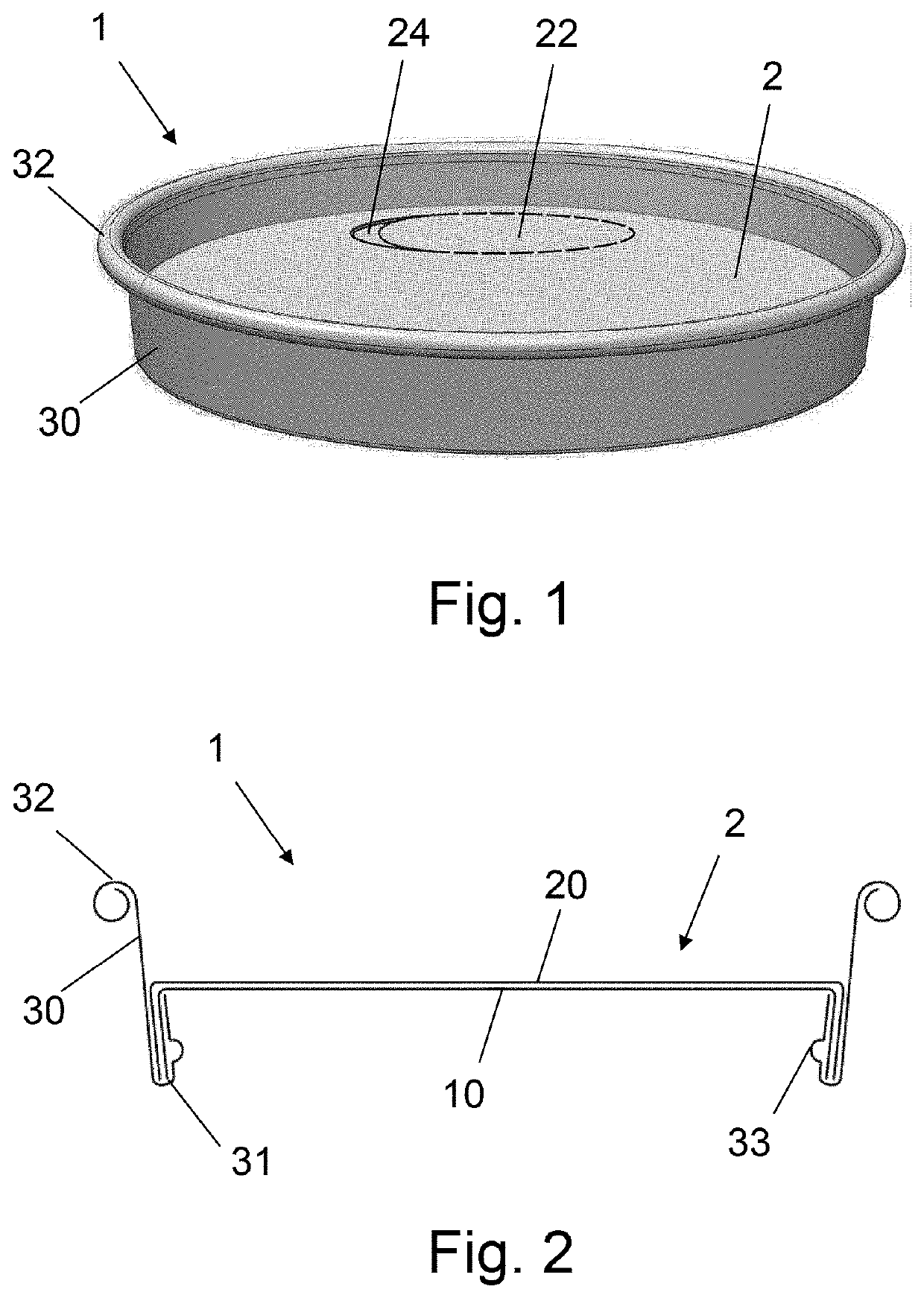
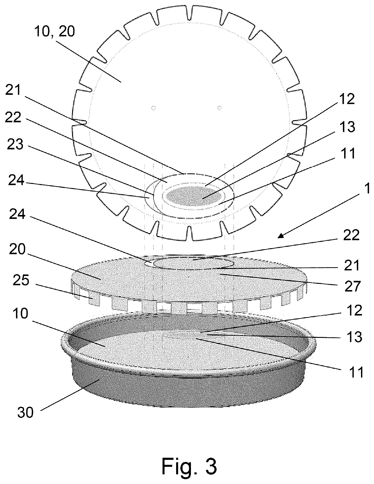
[0074]FIGS. 1 and 2 illustrate a lid 1 according to the invention. The lid 1 may comprise a top wall 2 that is suitable for covering an opening of a container, such as but not limited to, a beverage cup. The top wall 2 may have a circular shape with a perimeter that may be connected to a sidewall 30 of the lid 1. The sidewall 30 may have a top edge 32 that may be configured as a bent edge, such as a rolled edge. Additionally, the sidewall 30 may comprise a lower edge 32 that may be configured as a bent edge. According to one embodiment, the sidewall 30 may have a conical shape, wherein the diameter of the sidewall 30 is larger at the top bent edge 32 of the sidewall than at a lower bent edge 31 of the sidewall 30. Alternatively, the sidewall 30 may have a cylindrical shape, wherein the diameter of the sidewall 30 at the top bent edge 32 of the sidewall 30 is approximately equal to the diameter at a lower bent edge 31 of the sidewall 30. The top wall 2 may be bent or folded at its pe...
second embodiment
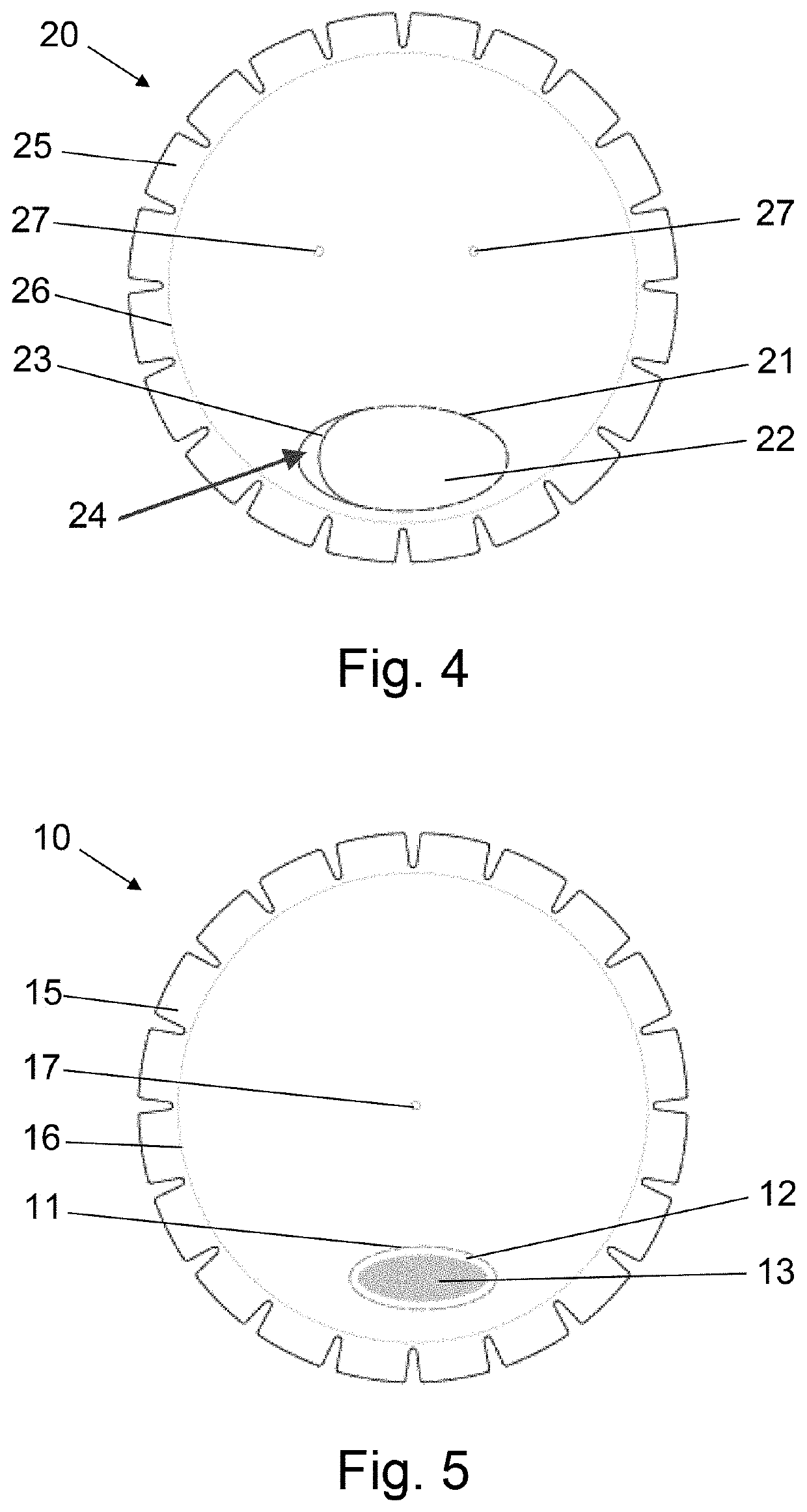
[0088]Additionally, according to lid 1, the first perforation line 11 of the inner layer 10, in a section 14 of the openable sip hole area 12 facing the grip recess 24, may comprise a larger perforation element than in a section of the openable sip hole area 12 oriented away from the grip recess 24. The larger perforation element may be provided as a cut line that facilitates removal of the sip hole area 12 when the sip hole area 12 is pulled by tearing off the tear-off area 22.
[0089]The lids 1 according to the first and second embodiments do not require a separate paper strip to be connected to the outside of the top wall 2. Rather, the sip hole 50 in the inner layer 10 can be reliably opened by tearing off the outer layer 20 of the top wall 2 of the lid as will be described with reference to FIG. 8-11.
[0090]FIG. 8 shows a package 9 comprising a container 5, which may be in the form of a paper cup for beverages, and a lid 1 covering an opening of the container 5. The lid 1 may be c...
third embodiment
[0095]The lid 1 may comprise a perforation line 21 with a first and a second perforation line end, wherein the first and second perforation line ends may each connect to a common crease line 29. The perforation line 21 and the crease line 29 may collectively define the tear-off area 22 of the outer layer 20. Furthermore, two additional crease lines 29′ and 29″ may be arranged in parallel to the crease line 29 in the tear-off area 22. The outer layer 20 may further comprise a slot 28 that may be arranged in parallel to the crease line 29. The slot 28 may be arranged such that a portion of the tear-off area 22 may be inserted into the slot 28 after separating the portion from the outer layer 20 and / or bending the tear-off area around the crease line 29. To facilitate introducing the tear-off area 22 into the slot, the slot 28 may have a width and two endings, wherein the width of the slot 28 may be smaller at the endings than at the middle of the slot 28. When the tear-off area 22 is...
PUM
| Property | Measurement | Unit |
|---|---|---|
| Distance | aaaaa | aaaaa |
| Distance | aaaaa | aaaaa |
| Angle | aaaaa | aaaaa |
Abstract
Description
Claims
Application Information
 - R&D
- Intellectual Property
- Life Sciences
- Materials
- Tech Scout
- Unparalleled Data Quality
- Higher Quality Content
- 60% Fewer Hallucinations
Browse by: Latest US Patents, China's latest patents, Technical Efficacy Thesaurus, Application Domain, Technology Topic, Popular Technical Reports.
© 2025 PatSnap. All rights reserved.Legal|Privacy policy|Modern Slavery Act Transparency Statement|Sitemap|About US| Contact US: help@patsnap.com


