Electric beard trimmer

a technology of electric shaver and electric trimmer, which is applied in the direction of metal working apparatus, etc., can solve the problems of not being able to achieve the effect of reducing the risk of skin irritation, not allowing for a more aggressive shave, and not being able to use the projecting teeth substantially perpendicular to the skin surface without causing skin irritation. , to achieve the effect of reliable and clean cutting action, avoiding skin irritation, and good control of edging

Pending Publication Date: 2021-07-29
BRAUN GMBH
View PDF8 Cites 6 Cited by
  • Summary
  • Abstract
  • Description
  • Claims
  • Application Information

AI Technical Summary

Benefits of technology

[0009]It is an objective underlying the present invention to provide for an improved cutter system avoiding at least one of the disadvantages of the prior art and / or further developing the existing solutions. A more particular objective underlying the invention is to provide for a close and thorough cutting of longer stubbles and hair including a good control of edging contours and, at the same time, avoiding skin irritations. Another objective underlying the present invention is a reliable and clean cutting action of the cooperating cutting teeth to avoid pulling and tugging of hair, without sacrificing low friction between the cutting elements, low temperatures of the cutting teeth and low energy consumption and thus long energy storage life.
[0010]To achieve at least one of the aforementioned objectives, the comb-like cutting elements have an improved tooth tips structure to allow for a closer, more aggressive cutting action on the one hand and a pleasant skin feel with prevention of skin piercing and reliable catching of problem hair on the other hand, depending on the user's preferences. More particularly, the cutting elements include two comb-like rows of cooperating cutting teeth which are configured asymmetrical to each other to achieve different performances. Said two rows of cooperating cutting teeth may be different from each other in terms of shape and / or size and / or positioning of the thickened and / or rounded tooth tips overhanging the tooth tips of the cooperating teeth. Thus, using a first row of cooperating cutting teeth may provide for a more aggressive, closer cutting action, whereas using a second row of cutting teeth may provide for a less intensive, more pleasant skin feel.
[0011]As the skin contact pressure may not be the same over the entire length of a teeth row, the tooth configuration may vary in the same row of cooperating teeth. More particularly, at least one row of cooperating teeth may include cutting teeth of different configurations, wherein cutting teeth in a middle section of said row may differ from the cutting teeth in end sections of said row in terms of shape and / or size and / or positioning of the tooth tips. Depending on the contour of the skin contact surface of the cutter head, the skin contact pressure at the end sections of a row of cooperating teeth may be larger or smaller than the skin contact pressure in a middle section of said row. So as to achieve a uniform and efficient cutting in all sections, the teeth in sections having a relatively lower skin contact pressure may be configured to be more aggressive than teeth in sections having a relatively higher skin contact pressure. By means of more aggressive teeth in sections with lower skin contact pressure, closeness and thoroughness can be achieved, whereas less aggressive teeth in regions with higher skin contact pressure avoid skin irritations.
[0013]According to another aspect, closeness and thoroughness of the cutting action may be combined with a pleasant skin feel avoiding skin irritations, by means of a two-step rounding of the overhanging tooth tips including a spherical or drop shaped or pearl-shaped thickening and a bent or curved tooth portion connecting said thickening to a main tooth portion and bent or curved away from the skin contact surface of said main tooth portion. A slight concave or flattened depression may be formed in the transition section between the ball-shaped thickening and said bent or curved tooth portion. Bending the teeth away from the skin contact surface in addition to the provision of a substantially spherical or drop shaped thickening at the outermost tip portion reliably prevents skin piercing and skin irritations even when using smaller sized thickening and / or rounding contours, but nevertheless allows for closeness and thoroughness of the cutting action. More particularly, the substantially spherical thickening may form the very outermost tip portion, wherein a more inwardly positioned tip portion neighboring said thickening may be bent away from the skin surface of the main tooth portion. Said more inwardly positioned tip portion is still part of the tooth tip, but is not yet part of the thickening and may have a substantially flat, plate-like configuration with a thickness comparable to or the same as the inner portions or main portion of the cutting tooth. The term “bent” in this and the following context can be substituted by “curved” and only optionally but not necessarily may also refer to the process of bending in order to create the curved or bent shape.

Problems solved by technology

Fulfilling such various performance issues at the same time is quite difficult.
For example, rounded tooth tips with thickened end portions as shown in EP 27 47 958 B1 may prevent skin irritations, but do not allow for a more aggressive, closer shave.
On the other hand, cutter systems with relatively sharp tooth tips at the upper driven comb as shown in US 2017 / 0050326 A1 may achieve closeness, but cannot be used to cut contours with the projecting teeth substantially perpendicular to the skin surface without causing skin irritations.

Method used


Image

  • Electric beard trimmer
  • Electric beard trimmer
  • Electric beard trimmer

Examples


Embodiment Construction

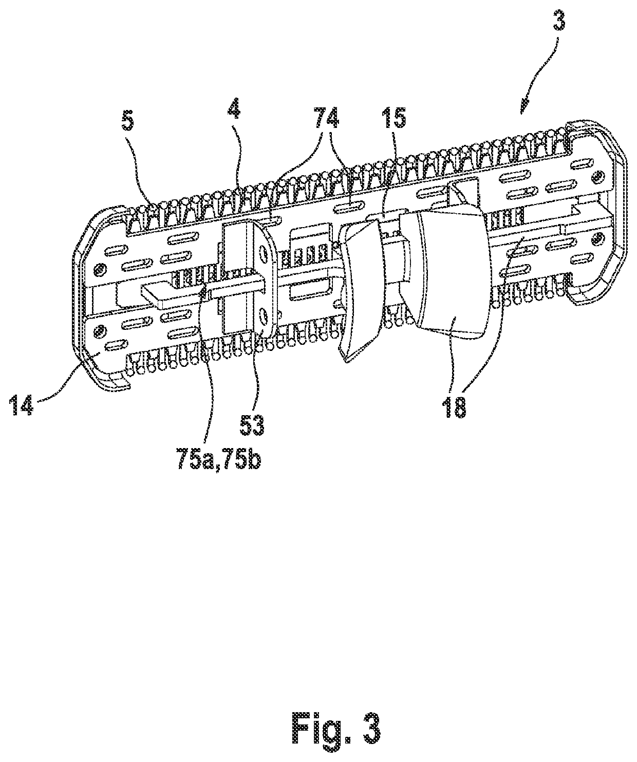
[0032]So as to give the user the choice between a more aggressive, closer cutting action on the one hand and a less intensive, more pleasant skin feel on the other hand, the cutter system provides for two separate rows of cooperating teeth which are different from each other in terms of shape and / or size and / or positioning of the thickened and / or rounded tooth tips of the teeth. Thus, using a first row of cooperating cutting teeth may provide for a more aggressive, closer cutting action, whereas using a second row of cutting teeth may provide for a less intensive, more pleasant skin feel. The configuration of the tooth tips, in particular the configuration of the curvature and thickening thereof may considerably influence the cutting performance and allow the user to choose between closeness, thoroughness, soft skin feel and efficiency. Due to the at least two rows of cooperating teeth having tooth tips configured differently aggressive, versatility of the cutter system is significa...


PUM


Abstract

The present invention relates to a cutter system for an electric shaver and / or trimmer, comprising a pair of comb-like cutting elements each with at least one row of cutting teeth and movable relative to each other, wherein at least one row of cooperating cutting teeth define a convex or concave skin contact surface when viewed in a cross-sectional plane parallel to a reciprocating direction of the cutting teeth and perpendicular to said skin contact surface.

Description

FIELD OF THE INVENTION[0001]The present invention relates to cutting body hair such as beard stubbles of multidays' beard. More particularly, the present invention relates to a cutter system for an electric shaver and / or trimmer, comprising a pair of comb-like cutting elements each with at least one row of cutting teeth and movable relative to each other, wherein one of said cutting elements has thickened and / or rounded tooth tips overhanging the tooth tips of the other cutting element.BACKGROUND OF THE INVENTION[0002]Electric shavers and trimmers utilize various mechanisms to provide hair cutting functionality. Some electric shavers include a perforated shear foil cooperating with an undercutter movable relative thereto so as to cut hairs entering the perforations in the shear foil. Such shear foil type shavers are often used on a daily basis to provide for a clean shave wherein short beard stubbles are cut immediately at the skin surface.[0003]On the other hand, other cutter syste...

Claims


Application Information

Patent Timeline
Patent Type & Authority Applications(United States)
IPC IPC(8): B26B19/10B26B19/04B26B19/06
CPCB26B19/10B26B19/06B26B19/046B26B19/3846B26B19/042
Inventor KOEPPL, ALOISEICHHORN, REINHOLDSCHMITT, JANAFUELLGRABE, MARTIN
Owner BRAUN GMBH
Why Eureka
Try Eureka