Image forming device and medium detecting mechanism thereof

a technology of image forming device and detecting mechanism, which is applied in the direction of instruments, electrographic process apparatus, optics, etc., can solve the problems of restricted moving range of moving components, inconvenient use, and inability to work normally

Active Publication Date: 2021-08-26
AVISION
View PDF3 Cites 0 Cited by
  • Summary
  • Abstract
  • Description
  • Claims
  • Application Information

AI Technical Summary

Benefits of technology

[0014]In summary, in the present invention, when the at least one medium enters into the medium entrance and abuts against the abutting end of the first pivoting component, the at least one medium drives the first pivoting component to pivot in the first pivoting direction to drive the second pivoting component to pivot in the first pivoting component by the resilient component for allowing the detecting end of the second pivoting component to actuate the detector to generate the signal. When the detecting end of the second pivoting component is stopped from continuously pivoting in the first pivoting direction, the resilient deformation of the resilient component allows the first pivoting component to be driven by the at least one medium to continuously pivot in the first pivoting direction relative to the second pivoting component. Therefore, the present invention can solve a problem of structural interference in the prior art and allow a user to place a large amount of the media at the medium entrance for preventing a multi-stage scanning operation or a multi-stage printing operation.

Problems solved by technology

However, a moving range of the moving component is restricted by an internal mechanical space of the image forming device, which only allows a user to place a small amount of media at the medium entrance.
When the user places an excessively large amount of media at the medium entrance, the moving component may interfere with another structure, so that the moving component cannot work normally.
If a printing operation or a scanning operation requires a large amount of media, the operation needs to be divided into multiple stages, which is not convenient in use.

Method used


Image

  • Image forming device and medium detecting mechanism thereof
  • Image forming device and medium detecting mechanism thereof
  • Image forming device and medium detecting mechanism thereof

Examples


Embodiment Construction

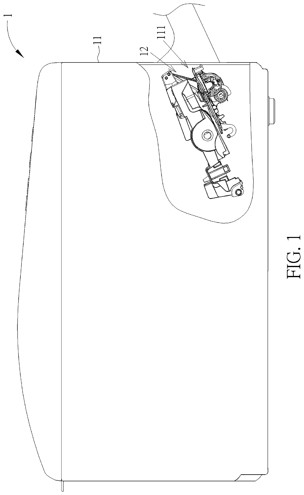
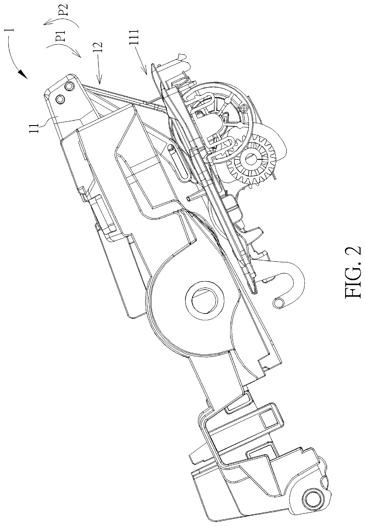
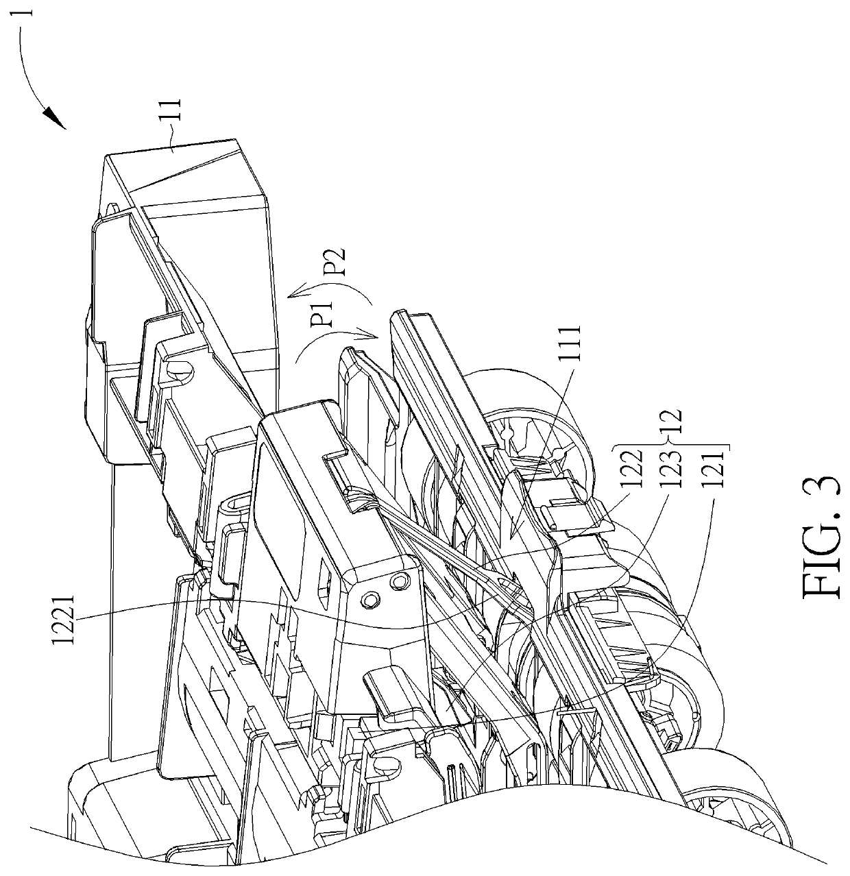
[0022]In the following detailed description of the preferred embodiments, reference is made to the accompanying drawings which form a part hereof, and in which is shown by way of illustration specific embodiments in which the invention may be practiced. In this regard, directional terminology, such as “top”, “bottom”, “front”, “back”, etc., is used with reference to the orientation of the Figure (s) being described. The components of the present invention can be positioned in a number of different orientations. As such, the directional terminology is used for purposes of illustration and is in no way limiting. Accordingly, the drawings and descriptions will be regarded as illustrative in nature and not as restrictive. Also, the term “connect” is intended to mean either an indirect or direct electrical / mechanical connection. Thus, if a first device is connected to a second device, that connection may be through a direct electrical / mechanical connection, or through an indirect electri...


PUM


Abstract

An image forming device includes a casing and a medium detecting mechanism. A medium entrance is formed on the casing. The medium detecting mechanism includes a detector, a first pivoting component, a second pivoting component and a resilient component. When at least one medium enters into the medium entrance and abuts against the first pivoting component, the at least one medium drives the first pivoting component to pivot in a first pivoting direction, so that the second pivoting component is driven by the resilient component to pivot in the first pivoting direction to actuate the detector for generating a signal. When the second pivoting component is stopped from pivoting in the first pivoting direction, deformation of the resilient component allows the first pivoting component to be driven by the at least one medium to pivot relative to the second pivoting component in the first pivoting direction continuously.

Description

BACKGROUND OF THE DISCLOSURE1. Field of the Disclosure[0001]The present invention relates to an image forming device and a medium detecting mechanism thereof, and more specifically, to an image forming device capable of detecting a large amount of media and a medium detecting mechanism.2. Description of the Prior Art[0002]Image forming devices, such as scanners or printers, are widely used in families or offices for bringing convenience in people's lives. The image forming device includes a detecting mechanism at a medium entrance for detecting at least one medium, such as paper, to provide a notification to remind a user of replenishment of at least one printing medium when the at least one printing medium runs out or to inform the user of scanning completion when finishing delivery of at least one scanning medium. The conventional detecting mechanism usually includes a detector and a moving component. The moving component can be driven by the at least one medium to actuate the det...

Claims


Application Information

Patent Timeline
Patent Type & Authority Applications(United States)
IPC IPC(8): G03G15/00
CPCG03G15/553H04N1/00687H04N1/00694H04N1/04G03G2215/00725G03G2215/00616B65H2553/41G03G15/607
Inventor LIN, CHIA-CHING
Owner AVISION
Why Eureka
Try Eureka