Connector mechanism with a guide hole structure, connector mechanism with a guide pin structure and related electronic device assembly

a technology of connecting mechanism and guide pin, which is applied in the direction of coupling device details, coupling device connection, instruments, etc., can solve the problems of motion deadlock, link paralysis, and difficult connection of external transmitters, and achieve the effect of reducing inspection costs and increasing product yield

Active Publication Date: 2015-10-20
WISTRON CORP
View PDF10 Cites 0 Cited by
  • Summary
  • Abstract
  • Description
  • Claims
  • Application Information

AI Technical Summary

Benefits of technology

[0019]The present disclosure utilizes specific design of the guide pin structure and the guide hole structure to avoid the structural interference between the plug connector and the receptacle connector, so as to avert unnecessary rework, economize inspection cost and increase product yield.

Problems solved by technology

Due to difference position of the two terminals, the external transmitter may be difficult to connect with the portable electronic device because of assembly tolerance.
However, movements of the male terminal and the female terminal are constrained when the guiding pin inserts into the guiding hole, and the conventional docking connector has drawbacks of motion deadlock and linking paralysis generated by structural interference.
Design of a docking connector capable of improving assembly inaccuracy of the guiding pin and the guiding hole is an important issue in the mechanical industry.

Method used


Image

  • Connector mechanism with a guide hole structure, connector mechanism with a guide pin structure and related electronic device assembly
  • Connector mechanism with a guide hole structure, connector mechanism with a guide pin structure and related electronic device assembly
  • Connector mechanism with a guide hole structure, connector mechanism with a guide pin structure and related electronic device assembly

Examples


Embodiment Construction

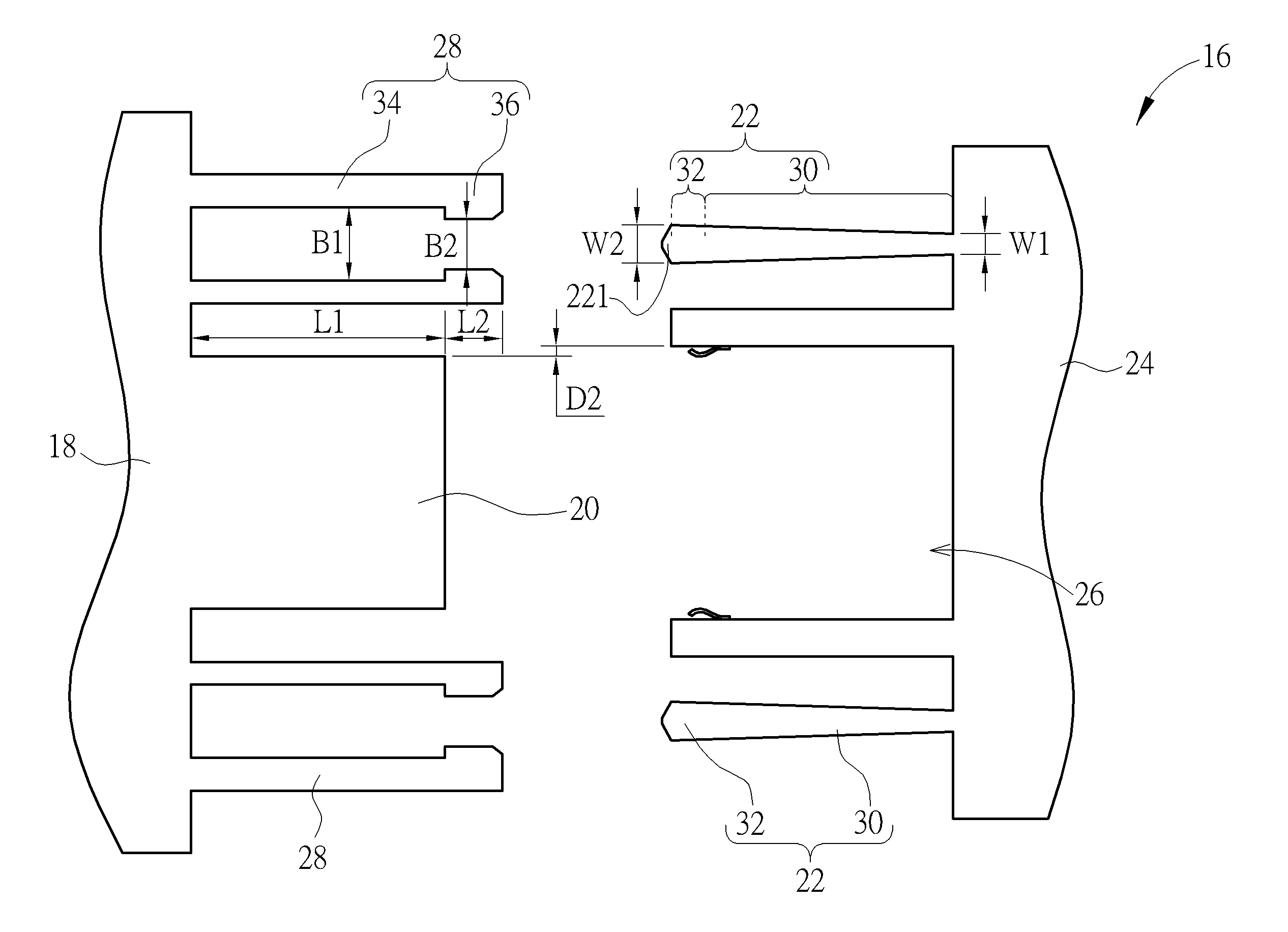
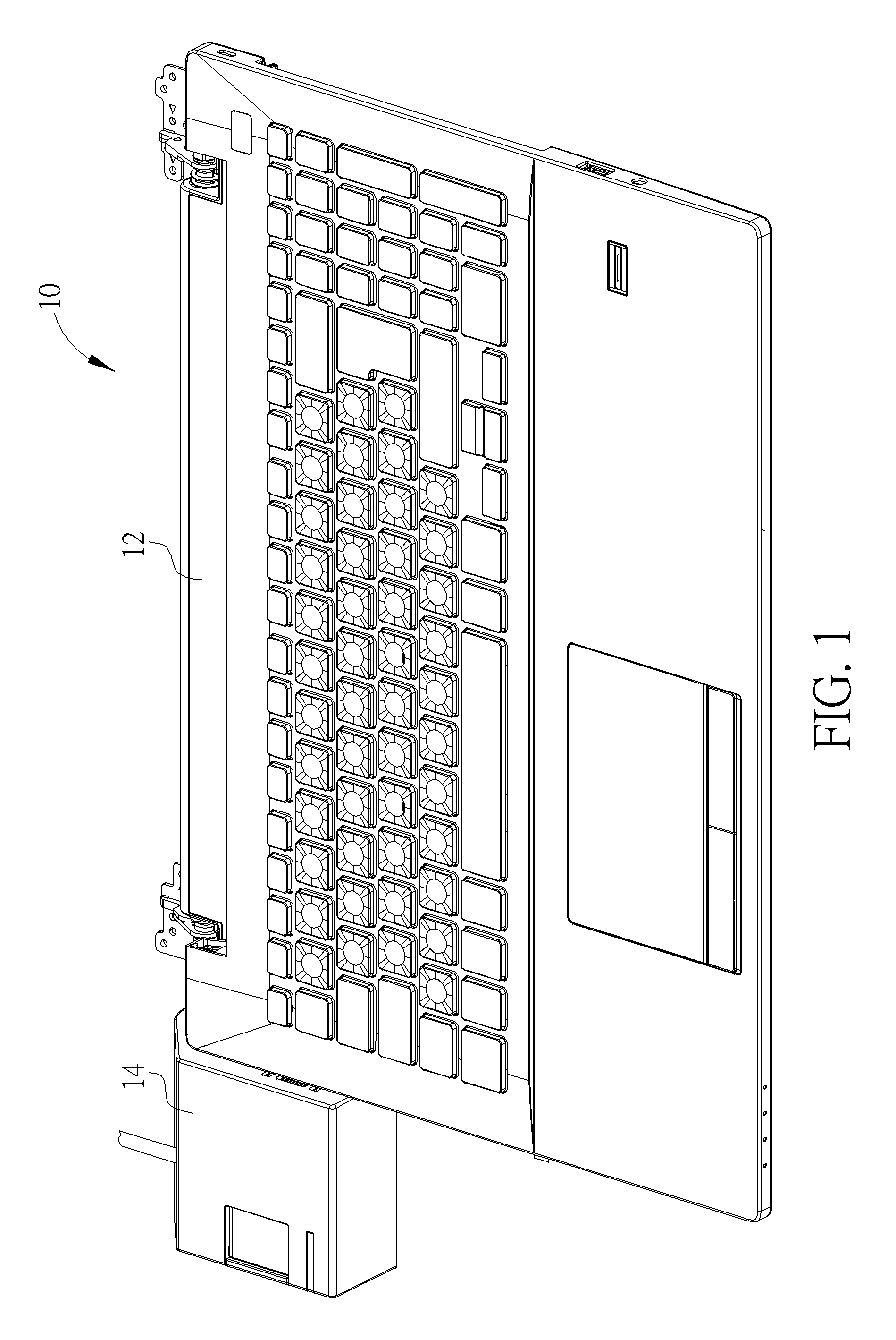
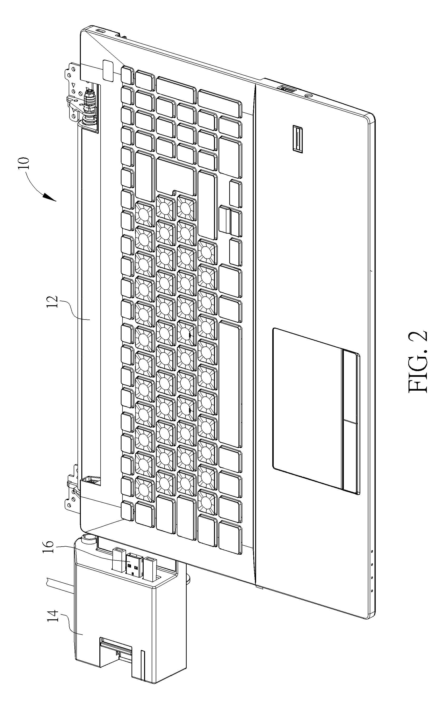
[0028]Please refer to FIG. 1 to FIG. 3. FIG. 1 and FIG. 2 are diagrams of an electronic device assembly 10 in different modes according to an embodiment of the present disclosure. FIG. 3 is another view of the electronic device assembly 10 shown in FIG. 2. The electronic device assembly 10 includes a portable electronic device 12, an external electronic device 14 and a connector mechanism 16. Generally, the portable electronic device 12 can be a notebook computer, a tablet computer, a smart phone, a personal digital assistance and so on. The external electronic device 14 can be a battery charger, a flash disk and / or a signal adapter. The external electronic device 14 can be detachably assembled with the portable electronic device 12 via the connector mechanism 16 for signal transmission or electric charge. The connector mechanism 16 in the present disclosure provides the specific guide pin / hole structures to effectively increase orientation accuracy and operational fluency of connec...


PUM


Abstract

A connector mechanism is utilized to connect with a portable electronic device with a receptacle connector and a guide pin structure. The guide pin structure includes a first portion and a second portion. The connector mechanism includes a base, a plug connector and a guide hole structure. The plug connector and the guide hole structure are disposed on the base. A length of the guide hole structure is greater than a length of the plug connector. The guide hole structure includes a first area and a second area. A width of the first area is greater than a width of the second area. Width difference between the plug connector and the receptacle connector is greater than width difference between the second portion and the second area, and is greater than width difference between the first portion and the second area and between the second portion and the first area.

Description

BACKGROUND OF THE INVENTION[0001]1. Field of the Invention[0002]The present disclosure relates to a connector mechanism, and more particularly, to a connector mechanism with special design for preventing the plug and the receptacle from structural interference.[0003]2. Description of the Prior Art[0004]A docking connector is usually applied to set between the portable electronic device and the external transmitter. A datum can be transmitted from a storage device to the portable electronic device via the external transmitter, or the portable electronic device can be charged by the commercial power via the external transmitter. The docking connector includes a male terminal and a female terminal, respectively disposed on the portable electronic device and the external transmitter. Due to difference position of the two terminals, the external transmitter may be difficult to connect with the portable electronic device because of assembly tolerance. For avoid the above-mentioned drawbac...

Claims


Application Information

Patent Timeline
Patent Type & Authority Patents(United States)
IPC IPC(8): H01R13/64H01R13/631H01R24/66G06F1/16
CPCH01R13/631G06F1/1632H01R24/66H01R13/6315
Inventor CHEN, HUNG-SHENGJUANG, JIAN-SHIANG
Owner WISTRON CORP
Why Eureka
Try Eureka