Keyswitch support connection structure and keyswitch structure therewith

a keyswitch and support technology, applied in the field of keyswitch structures, can solve the problems of increasing the degree of structural interference with the joining portion, and achieve the effects of increasing the structural interference of the joining portion, and increasing the structural interferen

Active Publication Date: 2021-09-30
DARFON ELECTRONICS CORP
View PDF0 Cites 0 Cited by
  • Summary
  • Abstract
  • Description
  • Claims
  • Application Information

AI Technical Summary

Benefits of technology

[0004]An objective of the invention is to provide a keyswitch support connection structure, which uses a wing portion that protrudes from a bottom plate portion and extends parallel to the bottom plate portion to increase the structural joining strength.
[0005]A keyswitch support connection structure according to the invention includes a bottom plate portion and a joining portion. The bottom plate portion has a bottom surface, an upper surface opposite to the bottom surface, and a joining hole passing through the bottom surface and the upper surface. The joining portion and the joining hole are firmly engaged with each other. The joining portion has a wing portion protruding from the bottom surface and extending parallel to the bottom surface. The joining portion and the bottom plate portion jointly form or the joining portion alone forms a support connection portion on the upper surface. Therein, the wing portion can increase the degree of structural interference of the joining portion with the bottom plate portion, and also can increase the joining strength between the joining portion and the bottom plate portion, which helps to maintain the structural stability of the support connection portion.
[0006]Another objective of the invention is to provide a keyswitch support connection structure, which uses an upwardly-extending cantilever plate or a protruding bridge portion across a joining hole to increase the structural joining strength.
[0007]A keyswitch support connection structure according to the invention includes a bottom plate portion, a joining structure, and a joining portion. The bottom plate portion has a joining hole. The joining structure is disposed at the joining hole. The joining structure includes at least one cantilever plate or at least one protruding bridge portion. The cantilever plate is a single-planar structure, extends upward from the joining hole and has a holding structure. The protruding bridge portion is connected across two sides of the joining hole. The joining portion and the joining hole are firmly engaging with each other. The joining portion encapsulates the at least one cantilever plate or the at least one protruding bridge portion. The joining portion includes two hook portions, of which two opposite concave wall surfaces jointly define a shaft recess to form a support connection portion. Therein, the cantilever plate itself can increase the surface area in contact with the joining portion, and the holding structure can increase the degree of structural interference with the joining portion. Both can increase the joining strength of the joining portion

Problems solved by technology

Therein, the cantilever plate itself can increase the surface area in contact with the joining portion,

Method used


Image

  • Keyswitch support connection structure and keyswitch structure therewith
  • Keyswitch support connection structure and keyswitch structure therewith
  • Keyswitch support connection structure and keyswitch structure therewith

Examples


first embodiment

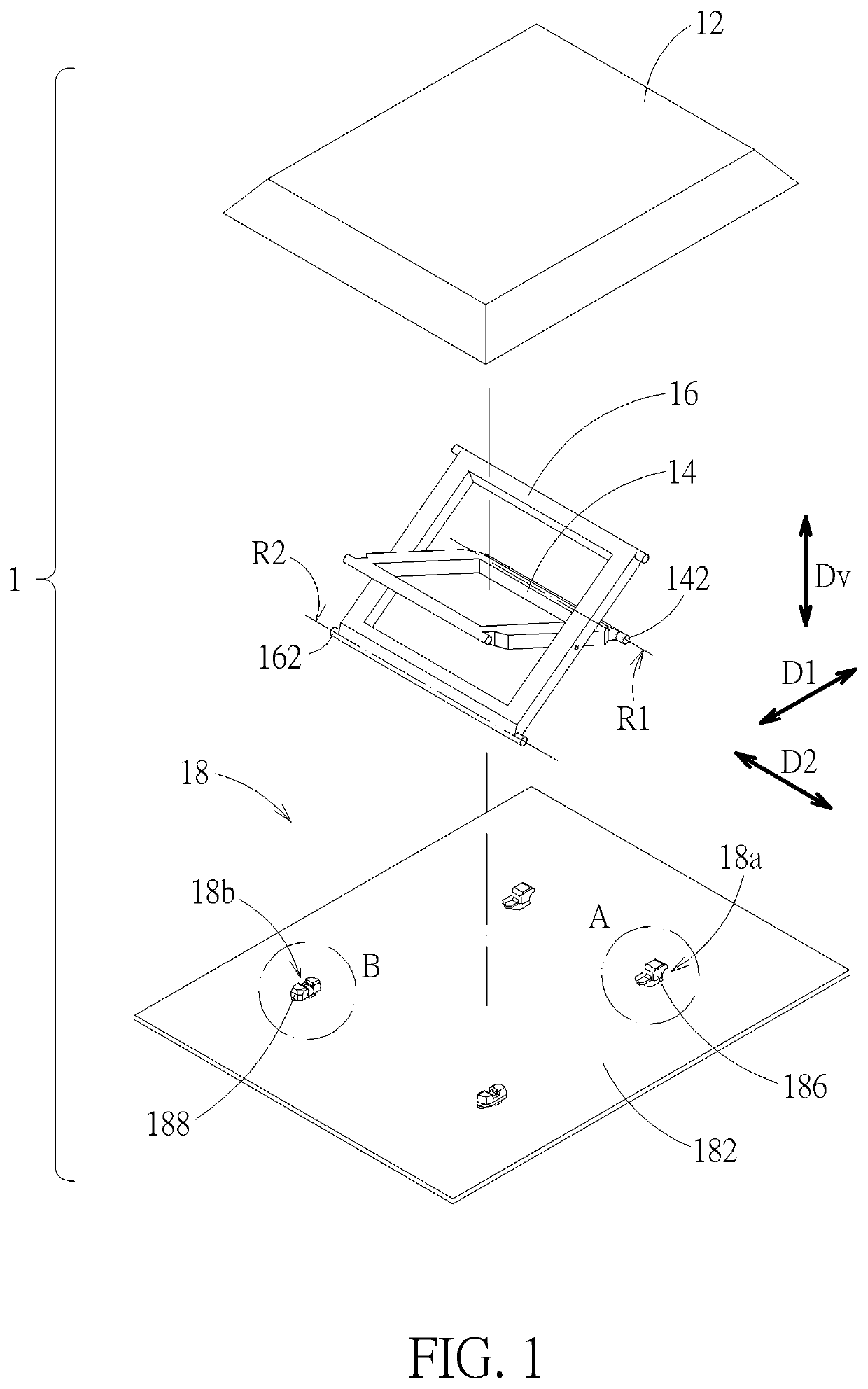
[0029]Please refer to FIG. 1. A keyswitch structure 1 includes a keycap 12, a first keyswitch support 14, a second keyswitch support 16, and a base 18. The keycap 12 is disposed above the base 18. Both the first keyswitch support 14 and the second keyswitch support 16 are connected to and between the keycap 12 and the base 18, so that the keycap 12 can move vertically relative to the base 18 (or move parallel to a vertical direction Dv, indicated by a double-headed arrow in the figure) through the first keyswitch support 14 and the second keyswitch support 16. Therein, the base 18 includes two support connection portions 18a and two support connection portions 18b. The first keyswitch support 14 is rotatably and slidably connected to the base 18 through the support connection portion 18a. The second keyswitch support 16 is rotatably connected to the base 18 through the support connection portion 18b.

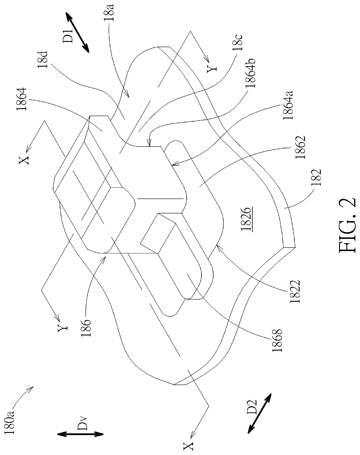
[0030]Please also refer FIG. 2 to FIG. 5. For the support connection portion 18a t...

eighth embodiment

[0050]Please refer to FIG. 18, which is a sectional view of an eighth embodiment, and of which the position of the cutting plan is equivalent to the line X-X in FIG. 2. FIG. 18 is roughly similar to the embodiment corresponding to FIG. 4. The difference relative to FIG. 4 is that the joining hole 1822 (referring FIG. 4) is further provided with a protruding bridge portion 1830a (i.e., the protruding bridge portion 1830 in FIG. 7 and FIG. 8). The protruding bridge portion 1830a is connected across two sides of the joining hole 182, which divides the joining hole 1822 into two portions from the view in the vertical direction Dv. That is, the protruding bridge portion 1830a divides the joining hole 1822 into exposed middle hole 1822b and side hole 1822c in the first direction D1. The middle hole 1822b and the side hole 1822c are connected by the space under the protruding bridge portion 1830a. The embedded portion 1862 fills up the middle hole 1822b, the side hole 1822c, and the connec...


PUM


Abstract

A keyswitch support connection structure incudes a bottom plate portion and a joining portion firmly joined with a joining hole of a bottom plate portion to form a support connection portion. In an embodiment, a cantilever plate extends upward from the joining hole. The joining portion encapsulates a holding structure of the cantilever plate. In another embodiment, a protruding bridge portion connected across two sides of the joining hole. The joining portion encapsulates the protruding bridge portion. In another embodiment, the joining portion has a wing portion protruding from a bottom surface of the bottom plate portion and extending parallel to the bottom surface. A keyswitch structure includes a base with the keyswitch support connection structure, a keycap, and two keyswitch supports. The two keyswitch supports are connected to and between the keycap and the base; therein, one of the keyswitch supports is rotatably connected to the support connection portion.

Description

CROSS REFERENCE TO RELATED APPLICATIONS[0001]This application claims the benefit of U.S. Provisional Application No. 63 / 002,378 filed on Mar. 31, 2020, Application No. 63 / 005,473 filed on Apr. 6, 2020, Application No. 63 / 046,705 filed on Jul. 1, 2020, and Application No. 63 / 061,143 filed on Aug. 4, 2020 which are incorporated herein by reference.BACKGROUND OF THE INVENTION1. Field of the Invention[0002]The present invention relates to a keyswitch structure, and more particularly to a keyswitch support connection structure of a keyswitch structure.2. Description of the Prior Art[0003]A keyboard keyswitch structure of general notebooks usually uses a scissors-type support for providing a supporting and lifting mechanism for its keycap. For saving space, the structure bottom plate is usually used directly to form a structure which is used for connecting with the support, so that the support can be rotatably connected to the bottom plate. The bottom plate is generally formed by stamping...

Claims


Application Information

Patent Timeline
IPC IPC(8): H01H13/705H01H13/10H01H3/12
CPCH01H13/705H01H3/12H01H13/10H01H3/125H01H2209/01H01H13/14
Inventor HOU, PO-CHUNLIN, CHIN-HUNGYEH, LIANG-TACHAO, LING-HSI
Owner DARFON ELECTRONICS CORP
Why Eureka
Try Eureka