
PTFE heat exchanger

A technology of heat exchangers and heat exchange tubes, which is applied to the types of heat exchangers, heat exchanger shells, indirect heat exchangers, etc., can solve problems such as easy failure, plate corrosion, and heavy steel structures, and achieve a wide range of applications Effect

Active Publication Date: 2017-05-17
浙江赛迅环保科技有限公司
View PDF7 Cites 2 Cited by
  • Summary
  • Abstract
  • Description
  • Claims
  • Application Information

AI Technical Summary

Problems solved by technology

[0004] In the prior art, only metal plates are often used to separate the flue gas, which will easily cause corrosion of the plates after a long time, and the seals are also prone to failure when they are exposed to the flue gas environment for a long time
[0005] People use heat exchange tubes made of PTFE to overcome the problem of flue gas corrosion, but PTFE material is not soluble and will be liquefied directly at a certain temperature, so it is still necessary to use the outer plate of the steel structure as the skeleton skeleton. For example, the authorized announcement number is The Chinese utility model patent of CN202853458 U discloses a connection structure between the equipment body of the air-gas heat exchanger and the external steel structure. In this case, the external steel structure is not only heavy, but also greatly increases the cost of the heat exchanger.

Method used


Image

  • PTFE heat exchanger
  • PTFE heat exchanger
  • PTFE heat exchanger

Examples


Embodiment 1

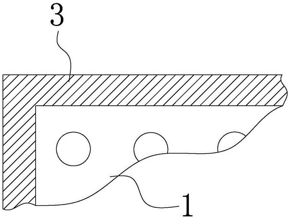
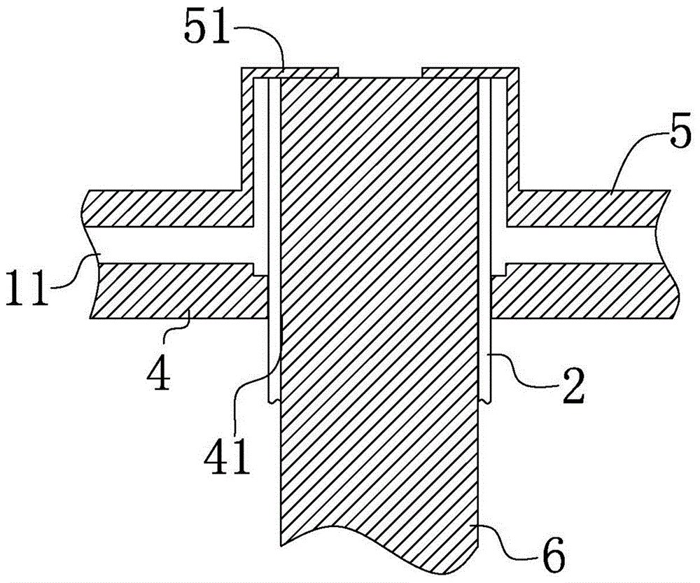
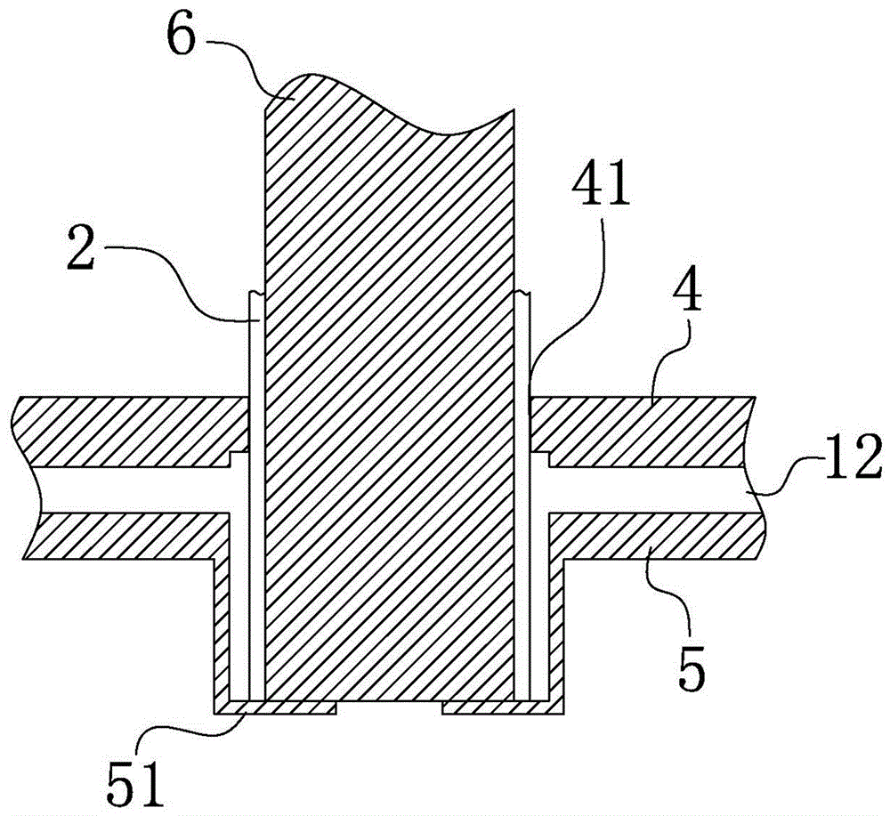
[0037] Example 1: Reference Figure 1~Figure 3 , a PTFE tubular heat exchanger, including a tube sheet 1 made of polytetrafluoroethylene material, a plurality of tube holes are opened on the tube sheet 1, and a polytetrafluoroethylene material is arranged in the tube hole The heat exchange tube 2; the error of the inner diameter, outer diameter, and wall thickness between the heat exchange tubes 1 is less than plus or minus 0.1 mm, and the wall thickness is 1 mm.

[0038] The heat exchange tube 2 and the tube sheet 1 are welded together by PFA material and auxiliary tools;

[0039] The auxiliary tools include: a frame-shaped tube sheet expansion limiting mold 3;

[0040] A tube plate supporting tray 4, on which are provided with a plurality of position-limiting holes 41 corresponding to the tube holes;

[0041] A plurality of tube sheet expansion limiting rings 5, the tube sheet expansion limiting rings 5 ​​are provided with heat exchange tube retaining rings 51;

[0042] A...

Embodiment 2

[0045] Example 2: Reference Figure 1~Figure 3 , a PTFE tube heat exchanger, the difference from Example 1 is: the wall thickness of the heat exchange tube 2 is 1.2 mm, and the tube sheet 1 includes an upper tube sheet 11 and a lower tube sheet 12, so The heat exchange tubes 2 are arranged between the upper tube sheet 11 and the lower tube sheet 12;

[0046] The heat exchange tube 2 and the upper tube sheet 11 are welded by an auxiliary tool;

[0047] The auxiliary tools include: a frame-shaped tube sheet expansion limiting mold 3;

[0048] A tube plate supporting tray 4, on which are provided with a plurality of position-limiting holes 41 corresponding to the tube holes;

[0049] A plurality of tube sheet expansion limiting rings 5, the tube sheet expansion limiting rings 5 ​​are provided with heat exchange tube retaining rings 51;

[0050] A plurality of heat-conducting steel cores 6 adapted to the inner diameter of the heat exchange tube;

[0051] When welding, insert t...


PUM

PropertyMeasurementUnit
Wall thicknessaaaaaaaaaa

Abstract

The invention discloses a PTFE heat exchanger and relates to the technical field of heat exchange equipment. The PTFE heat exchanger comprises a tube plate made from a PTFE material. A plurality of tube holes are formed in the tube plate. Heat exchange tubes made from the PTFE material are arranged in the tube holes. The heat exchange tubes and the tube plate are welded together through bonding materials. The PTFE is adopted as the raw material for the whole heat exchanger, so that the PTFE heat exchanger is low in weight, resistant to corrosion, high in strength of a connecting structure, and long in service life.

Description

technical field [0001] The invention relates to the technical field of heat exchange equipment, in particular to a PTFE heat exchanger. Background technique [0002] With the depletion of oil and coal, energy issues are becoming more and more prominent in front of people. In addition to the development of new energy sources, the conservation and reuse of existing energy sources have also become the focus of people's research. [0003] In energy utilization technology, a heat exchanger is a device for exchanging heat between hot and cold fluids without direct contact. The tube heat exchanger has a wide range of applications in the fields of coal-fired boilers, waste incineration power generation, etc. . [0004] In the prior art, only metal plates are often used to separate the flue gas, which will easily cause corrosion of the plates after a long time, and the seals are also prone to failure when exposed to the flue gas environment for a long time. [0005] People use heat...

Claims


Application Information

Patent Timeline
IPC IPC(8): F28D7/00F28F9/18F28F21/06F28F19/00
CPCF28D7/00F28F9/185F28F9/187F28F19/00F28F21/062
Inventor 徐淦芳
Owner 浙江赛迅环保科技有限公司
Learn More