Suction valve assembly of reciprocating compressor

A compressor, reciprocating technology, applied in variable capacity pump components, liquid variable capacity machinery, components of pumping devices for elastic fluids, etc., can solve problems such as compression cavity dead zone

Inactive Publication Date: 2005-11-30
LG ELECTRONICS INC
View PDF0 Cites 2 Cited by
  • Summary
  • Abstract
  • Description
  • Claims
  • Application Information

AI Technical Summary

Problems solved by technology

Therefore, in the case of fastening with bolts, there is a dead zone inside the compression chamber

Method used


Image

  • Suction valve assembly of reciprocating compressor
  • Suction valve assembly of reciprocating compressor
  • Suction valve assembly of reciprocating compressor

Examples


Embodiment Construction

[0037] Preferred embodiments of the present invention will be described in detail below with reference to the accompanying drawings.

[0038] The present invention allows for a number of suction valve embodiments, the most preferred of which will now be described.

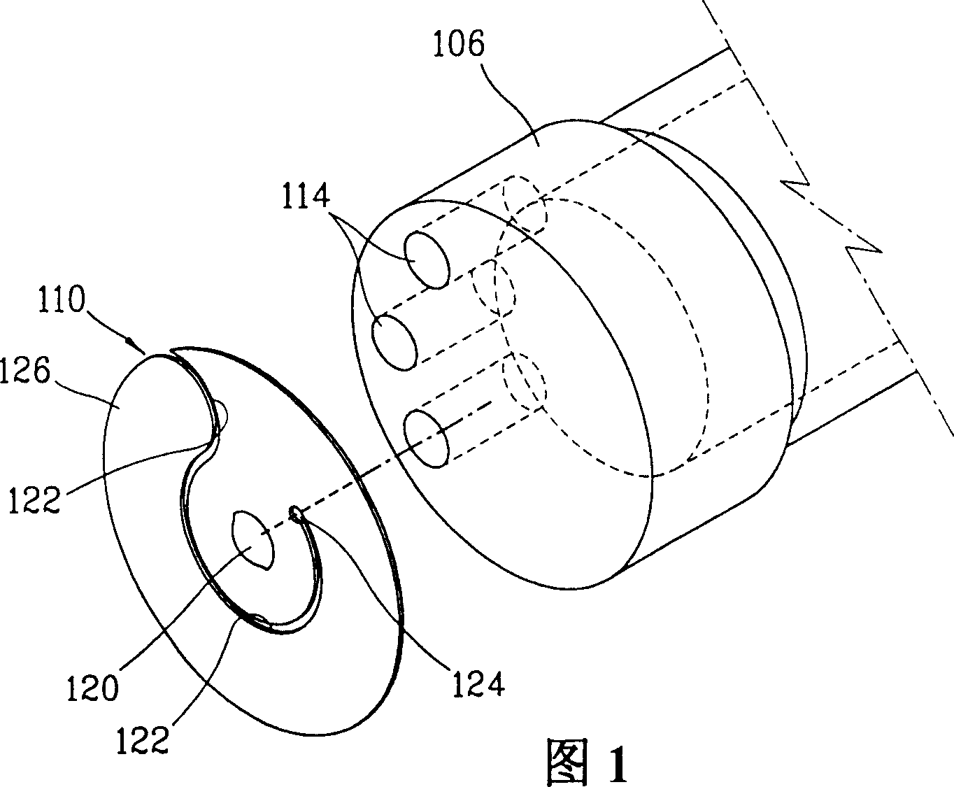
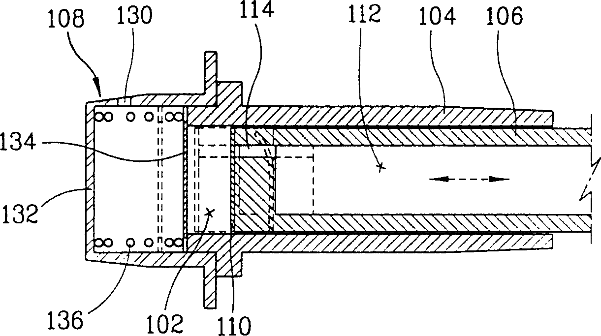
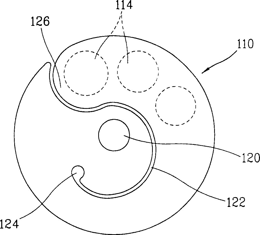
[0039] Figure 4 is a partial sectional view of a compressor having a suction valve assembly according to an embodiment of the present invention.

[0040] The compressor of the present invention comprises: a cylinder body 4 fixed on the compressor casing (not shown) and forming a compression chamber 2; a piston 6 linearly movable arranged in the cylinder body 4 and compressing fluid and forming a suction passage 8; The suction valve assembly 10 installed on the front side of the piston 6 supplies fluid to the compression chamber 2 when the piston moves backward, and prevents the backflow of the fluid inside the compression chamber 2 when the piston 6 moves forward; and the discharge valve installed on the front si...


PUM


Abstract

A suction valve assembly of a reciprocating compressor includes: an inertial valve having a valve plate detachably attached at a valve seat of a piston, and opening and shutting the suction passage, and a support bar extended from a rear side of the valve plate, inserted into the suction passage and a plurality of guide grooves at regular intervals in a circumferential direction thereof; and guide pins slidably inserted into the guide grooves of the inertial valve and fixed at the piston to limit an opening rate of the valve plate, thereby minimizing a dead volume inside a compression chamber by making a valve side forming the compression chamber to be plane and strengthening a structural coupling strength of a valve.

Description

field of invention [0001] The present invention relates to a suction valve assembly of a reciprocating compressor, and more particularly, to a suction valve assembly capable of preventing dead volume in a compression chamber and improving operational reliability of a reciprocating compressor. Background technique [0002] Generally, a suction valve assembly is installed between a compression chamber for compressing fluid and a suction passage for sucking fluid into a reciprocating compressor, so that when fluid is sucked, the suction valve assembly opens due to inertia, providing pressure from the compression chamber to the compression chamber. The fluid in the suction channel prevents the fluid compressed in the compression cavity from flowing back. [0003] Figure 1 is a partial cross-sectional view of a compressor with a suction valve assembly in the prior art, figure 2 is an exploded perspective view of a prior art suction valve, image 3 is a front view of a prior art...

Claims


Application Information

Patent Timeline
Patent Type & Authority Patents(China)
IPC IPC(8): F04B17/04F04B35/04F04B39/00F04B39/10
CPCF04B39/0016F04B39/102F04B17/04
Inventor 金炯镇
Owner LG ELECTRONICS INC
Why Eureka
Try Eureka