Phase-locked loop having phase detector error signal reshaping and method thereof

A technology of phase error and phase-locked loop, which is applied to the automatic control of power and electrical components, etc., can solve the problems of fast response time, unsatisfactory, and insufficient response time, and achieve the effect of reducing the dead zone

Inactive Publication Date: 2004-03-17
MEDIATEK INC
View PDF1 Cites 7 Cited by
  • Summary
  • Abstract
  • Description
  • Claims
  • Application Information

AI Technical Summary

Problems solved by technology

[0007] However, the known phase-locked loop still has the problem that the response time is not fast enough
More specifically, a phase-locked loop that uses both a frequency detector and a phase detector will still have frequencies in the frequency range where it cannot lock, and cannot meet the needs of faster response times

Method used


Image

  • Phase-locked loop having phase detector error signal reshaping and method thereof
  • Phase-locked loop having phase detector error signal reshaping and method thereof
  • Phase-locked loop having phase detector error signal reshaping and method thereof

Examples


Embodiment Construction

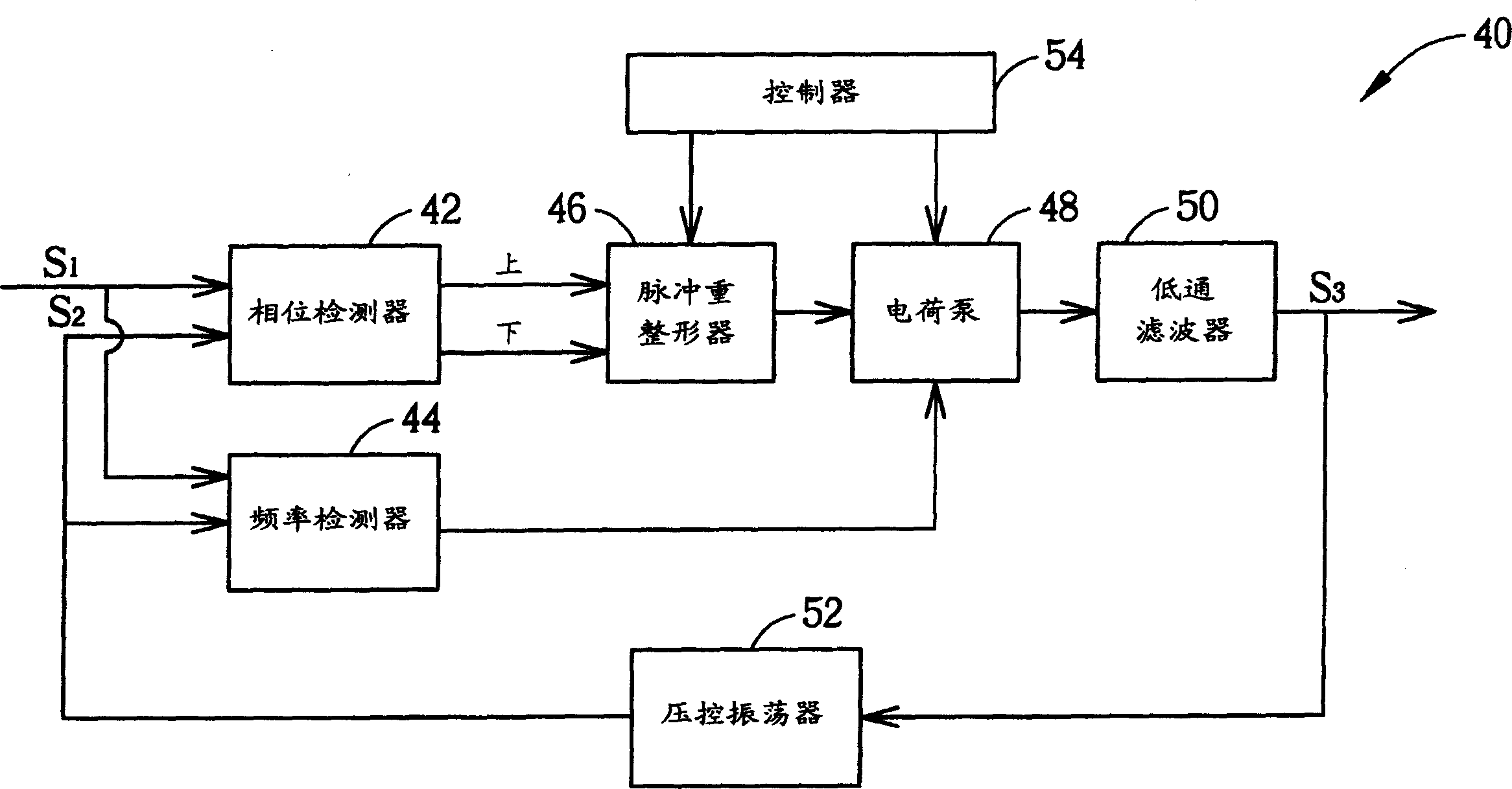
[0032] This paper will illustrate the present invention with two examples. The PLL of the first embodiment of the present invention includes a frequency detector and a controller, while the second embodiment does not have the controller. Furthermore, the first embodiment of the present invention utilizes a pulse reshaper as a signal reshaper.

[0033] see image 3 , image 3 It is a block diagram of a phase-locked loop 40 according to the first embodiment of the present invention. The PLL 40 includes a phase detector 42 and a frequency detector 44 for receiving an input signal S1 and a feedback signal S2. The phase detector 42 is connected to a pulse reshaper 46 that reshapes the pulses of the phase error signal from the phase detector 42 . The PLL 40 further includes a charge pump 48 which receives the signals from the pulse reshaper 46 and the frequency detector 44 and outputs a charge pump signal to the low-pass filter 50 . The low-pass filter 50 outputs an output sign...


PUM


Abstract

A phase-locked loop includes a signal reshaper connected between a phase detector and a charge pump. The signal reshaper can be controlled by a controller to reshape the phase error signal based on the difference between the frequency of an output signal, output from a low pass filter, and a target frequency. The signal reshaper outputs a reshaped or unreshaped phase error signal to the charge pump. The unreshaped phase error signal causes the phase-locked loop to lock the frequency of a feedback signal to the frequency of an input signal. The reshaped phase error signal causes the charge pump to output a charge pump signal that synchronizes the frequency of the output signal with the target frequency.

Description

technical field [0001] The present invention provides a phase-locked loop, particularly a phase-locked loop capable of reshaping a phase error signal and related methods. Background technique [0002] Phase-locked loops have been widely used in digital electronic instruments, signal telemetry devices, and communication technologies. In these applications, phase-locked loops are widely used in clock distribution, recovery, and data demodulation. [0003] The phase-locked loop is mainly used to generate an oscillation frequency that matches the frequency of an input signal. see figure 1 , figure 1 It is a block diagram of a basic PLL 10 known in the art. The PLL 10 includes a phase detector 12 for receiving an input signal S1 and a feedback signal S2 and comparing the phase difference between them. The phase detector 12 generates a phase error signal according to the phase difference. The PLL 10 further includes a frequency detector 13 for receiving the input signal S1 an...

Claims


Application Information

Patent Timeline
Patent Type & Authority Applications(China)
IPC IPC(8): H03L7/087H03L7/089H03L7/107
CPCH03L7/1072H03L7/087H03L7/0891H03L7/107
Inventor 何旭峰徐哲祥
Owner MEDIATEK INC
Why Eureka
Try Eureka