Lever assembly for optical scopes

Active Publication Date: 2021-10-07
FLATLINE OPS INC
View PDF0 Cites 3 Cited by
  • Summary
  • Abstract
  • Description
  • Claims
  • Application Information

AI Technical Summary

Benefits of technology

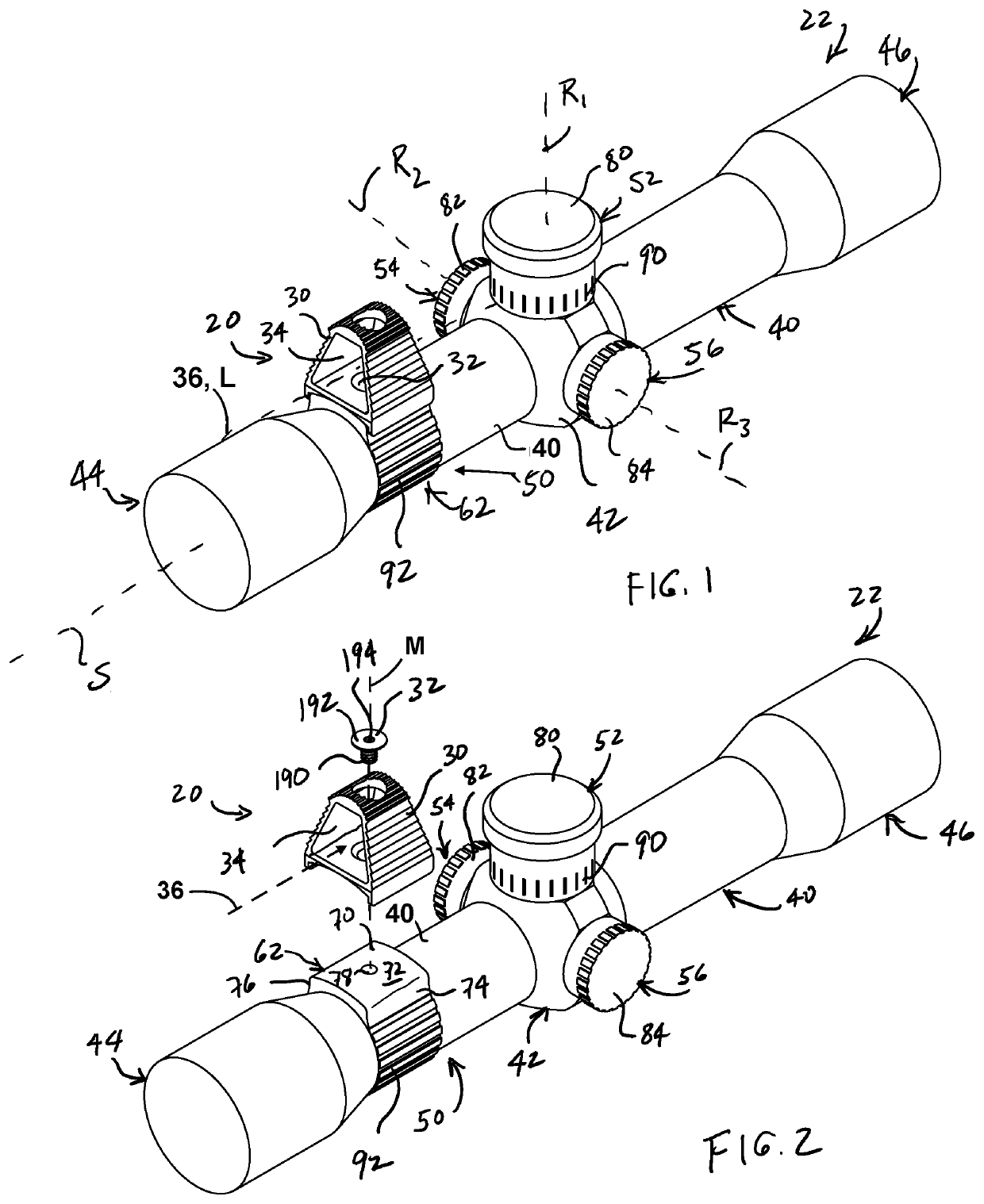
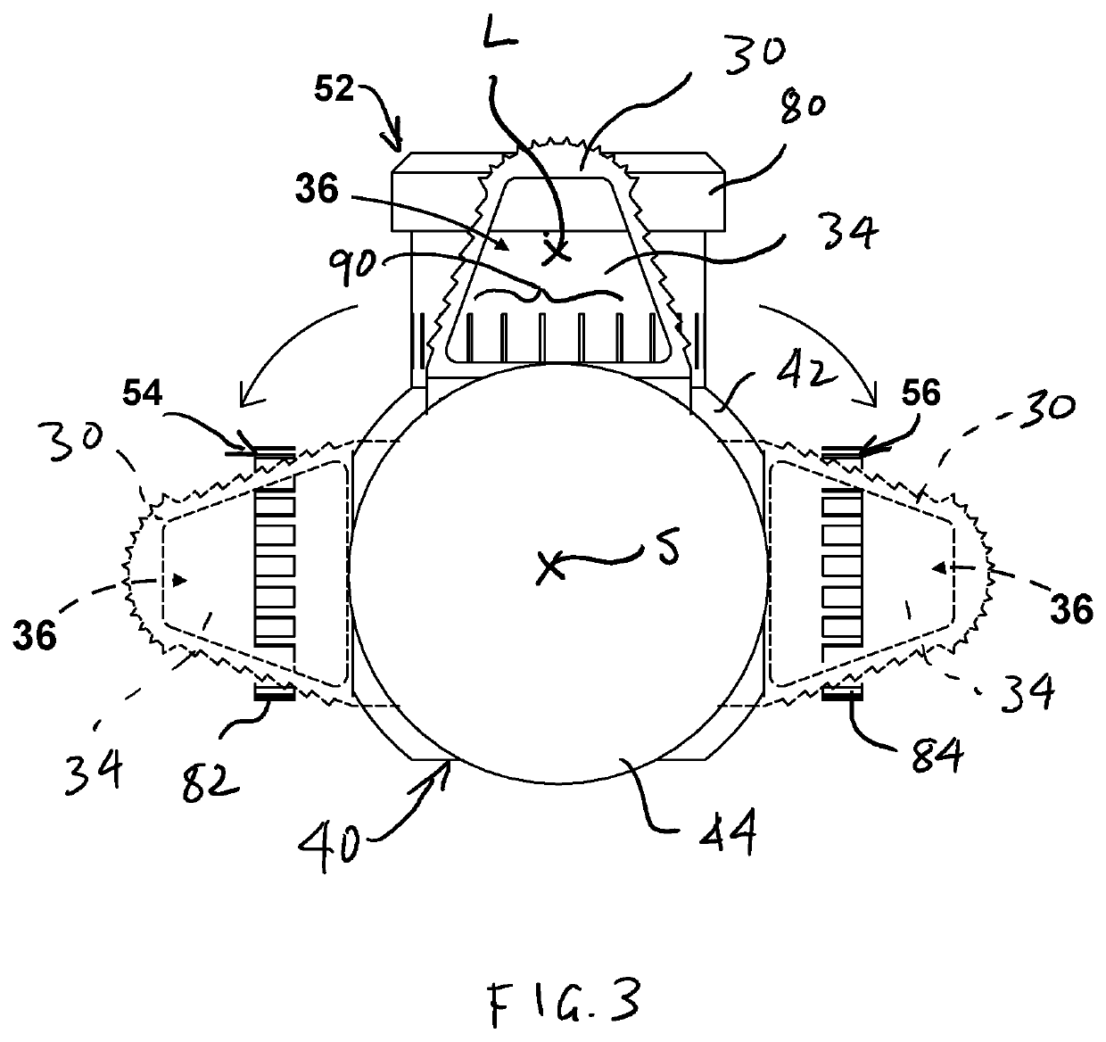
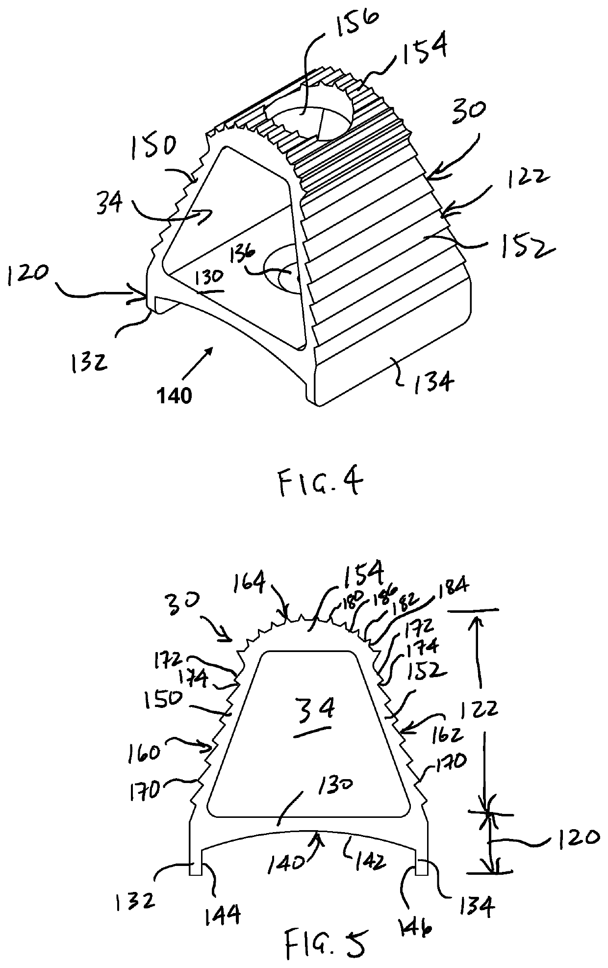
[0010]Disclosed herein is a lever assembly for an optical scope having a mounting surface, a mounting hole, and one or more windage, elevation, and/or parallax turrets with indicia thereon. The lever assembly includes a generally triangular lever member which defines a large central opening or window through which a user can easily view turret indicia along a sightline parallel to an axis of the optical scope when the lever assembly is secured to the scope. The lever member includes a base portion adapted to engage

Problems solved by technology

However, such collars can slip off of the magnification ring when bumped during use, while the throw lever arm can obstruct a user's view of the windage, elevation, and para

Method used


Image

  • Lever assembly for optical scopes
  • Lever assembly for optical scopes
  • Lever assembly for optical scopes

Examples


Example

[0025]While the making and using of various embodiments of the present invention are discussed in detail below, it should be appreciated that the present invention provides many applicable inventive concepts that are embodied in a wide variety of specific contexts. The specific embodiments discussed herein are merely illustrative of specific ways to make and use the invention and do not delimit the scope of the invention.

[0026]Those of ordinary skill in the art will recognize numerous equivalents to the specific apparatus and methods described herein. Such equivalents are considered to be within the scope of this invention and are covered by the claims.

[0027]To facilitate the understanding of the embodiments described herein, a number of terms are defined below. The terms defined herein have meanings as commonly understood by a person of ordinary skill in the portions relevant to the present invention. Terms such as “a,”“an,” and “the” are not intended to refer to only a singular en...


PUM


Abstract

A lever assembly for an optical scope defining a mounting surface, a mounting hole, and indicia, the lever assembly comprising a lever member and a mounting member. The lever member comprises a base portion comprising a base wall defining an engaging surface adapted to engage the mounting surface and an extension portion comprising at least one extension side wall extending from the base wall such that a lever sightline is defined by the base wall and the at least one extension side wall. The mounting member is adapted to secure the base wall to the mounting surface by engaging the mounting hole. The mounting member secures the lever member to the optical scope such that the indicia can be viewed along the lever sightline while the lever member is displaced through a range of movement to adjust the optical scope.

Description

CROSS-REFERENCES TO RELATED APPLICATIONS[0001]This non-provisional patent application claims priority to U.S. Provisional Patent Application Ser. No. 62 / 967,460, filed Jan. 29, 2020 and titled “LEVER ASSEMBLY FOR OPTICAL SCOPES,” the entire disclosure of which is hereby incorporated by reference.[0002]A portion of the disclosure of this patent document contains material that is subject to copyright protection. The copyright owner has no objection to the reproduction of the patent document or the patent disclosure, as it appears in the U.S. Patent and Trademark Office patent file or records, but otherwise reserves all copyright rights whatsoever.STATEMENT REGARDING FEDERALLY SPONSORED RESEARCH OR DEVELOPMENT[0003]Not Applicable.REFERENCE TO SEQUENCE LISTING OR COMPUTER PROGRAM LISTING APPENDIX[0004]Not Applicable.BACKGROUND OF THE INVENTION[0005]The present invention relates generally to the field of optical scopes, and more particularly, to throw levers for optical scopes for firear...

Claims


Application Information

Patent Timeline
IPC IPC(8): G02B23/16F41G1/38
CPCG02B23/16F41G1/38
Inventor MCCOY, II, CHARLES A.
Owner FLATLINE OPS INC
Why Eureka
Try Eureka