

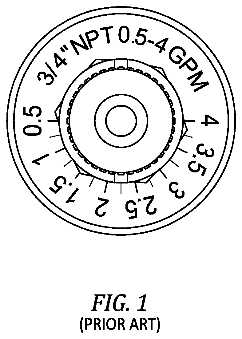
Flow rate scale field calibration for balancing valve
a flow rate scale and balancing valve technology, applied in the field of balancing valves, can solve the problems of adding a significant amount of time to system balancing, and difficult visual interpolation between the 8 numerically written increments and hash marks
- Summary
- Abstract
- Description
- Claims
- Application Information
AI Technical Summary
Benefits of technology
Problems solved by technology
Method used
Image

Examples
Embodiment Construction
FIGS. 2a to 2c
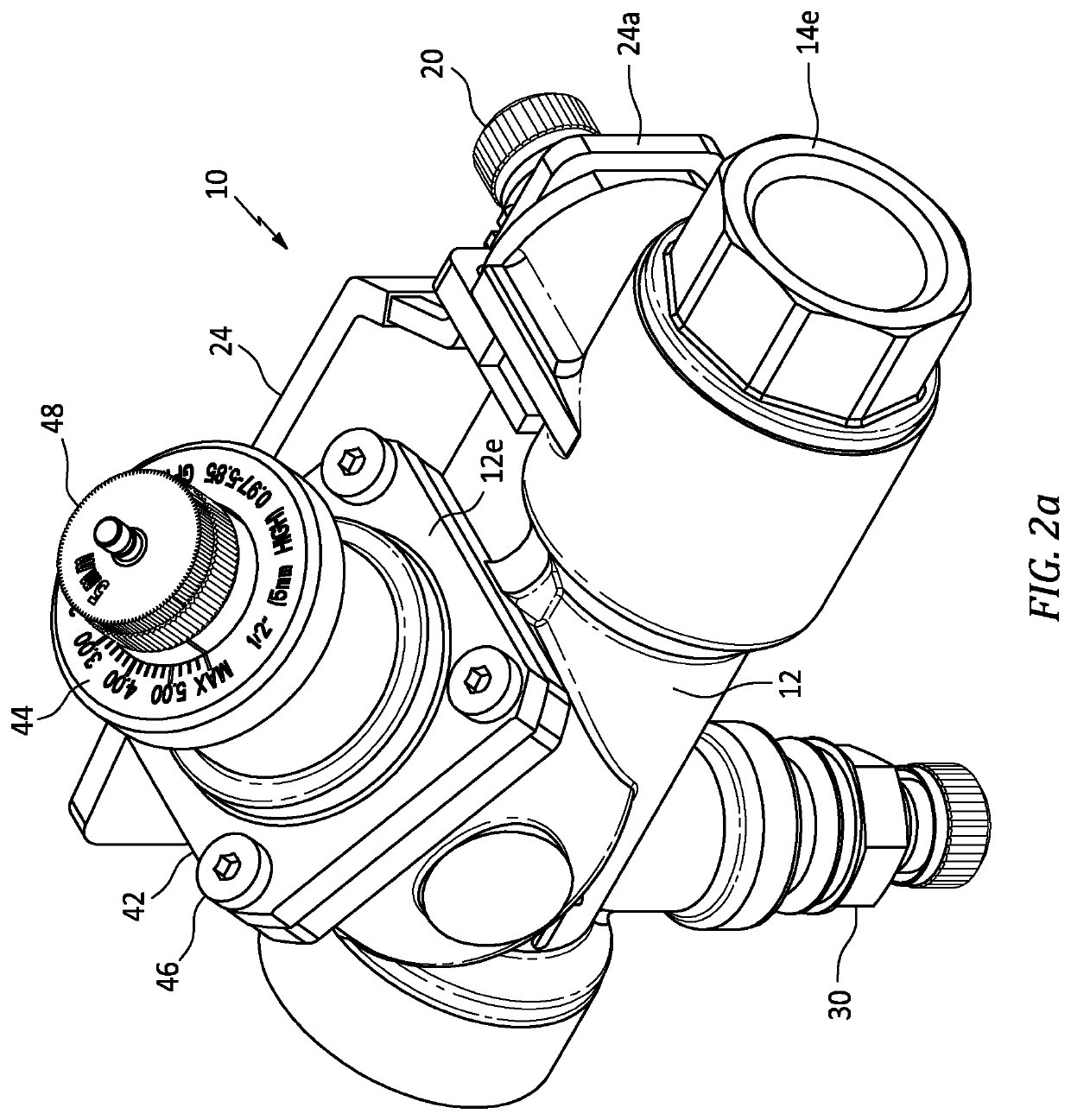
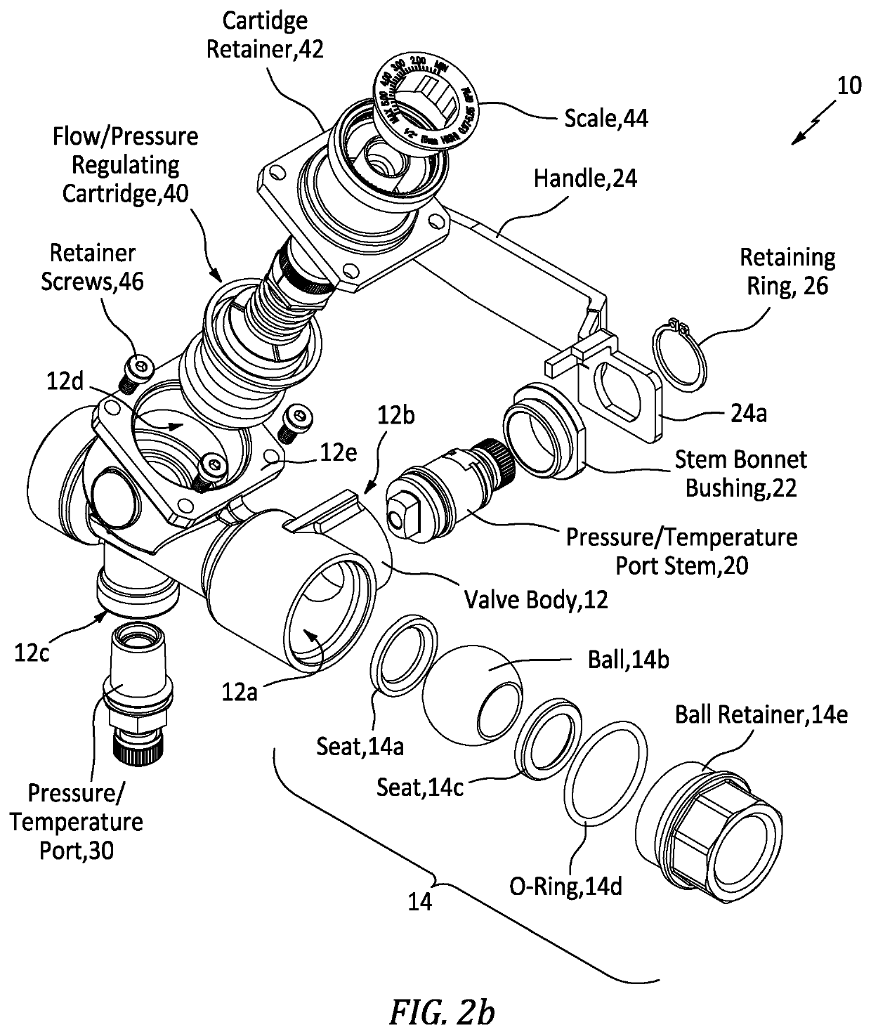
[0030]FIG. 2a-2c show apparatus generally indicated as 10 in the form of part of a balancing valve having a flow rate scale field calibration implementation according to some embodiments of the present invention. FIGS. 2a and 2b shows the parts and components of the balancing valve 10, and FIG. 2c shows a scale or indicator and a knob that forms part of the balancing valve shown in FIGS. 2a and 2b.
[0031]In FIGS. 2a and 2b, the balancing valve 10 includes a valve body / member 12 configured or formed with a first cavity or chamber generally indicated as 12a to receive a combination or arrangement generally indicated as 14 of a seal 14a, a ball 14b, a seat 14c, an O-ring 14d and a ball retainer 14e. The valve body 12 is also formed with a second cavity or chamber generally indicated as 12b and coupled to the first cavity or chamber 12a. The second cavity or chamber 12b is configured to receive a combination of a pressure / temperature port stem 20 and a stem bonnet bushing...
PUM
 Abstract
Description
Claims
Application Information