Image encoding apparatus, image decoding apparatus, and control method therefor

a technology of image encoding and decoding apparatus, applied in the field of image encoding and decoding an image, can solve the problems of reducing information, reducing image quality, and reducing image quality, so as to suppress the degradation of image quality and reduce information

Inactive Publication Date: 2012-08-07
CANON KK
View PDF26 Cites 2 Cited by
  • Summary
  • Abstract
  • Description
  • Claims
  • Application Information

AI Technical Summary

Benefits of technology

[0012]The present invention has been made to solve the aforementioned problems, and has as its object to provide an image encoding technique capable of reducing information much more than the conventional one while suppressing degradation of the image quality.
[0013]It is another object of the present invention to provide a technique capable of efficient compression.
[0016]According to the present invention, a block is scanned for each window having a size of p×q pixels, and encoded into p×q sub-block data each formed from pixel data at relatively identical positions in windows. Even if encoded data exceeds an allowable encoded data amount and encoded data of several sub-blocks are eliminated, the pixels of the eliminated sub-blocks can be easily interpolated from the pixels of existent surrounding sub-blocks.
[0017]The present invention can efficiently encode a complicated binary image.

Problems solved by technology

This appears as degradation of the image quality.
However, if an image is encoded at an excessively high compression ratio according to a lossy encoding method, many pieces of image information are omitted, and degradation of the image quality stands out.
These compression methods can efficiently compress simple images with high continuity, like a character or line image, but are not suitable for more complicated images.
In many cases, compression algorithms such as MH and MR are not suited to such an image.

Method used


Image

  • Image encoding apparatus, image decoding apparatus, and control method therefor
  • Image encoding apparatus, image decoding apparatus, and control method therefor
  • Image encoding apparatus, image decoding apparatus, and control method therefor

Examples


first embodiment

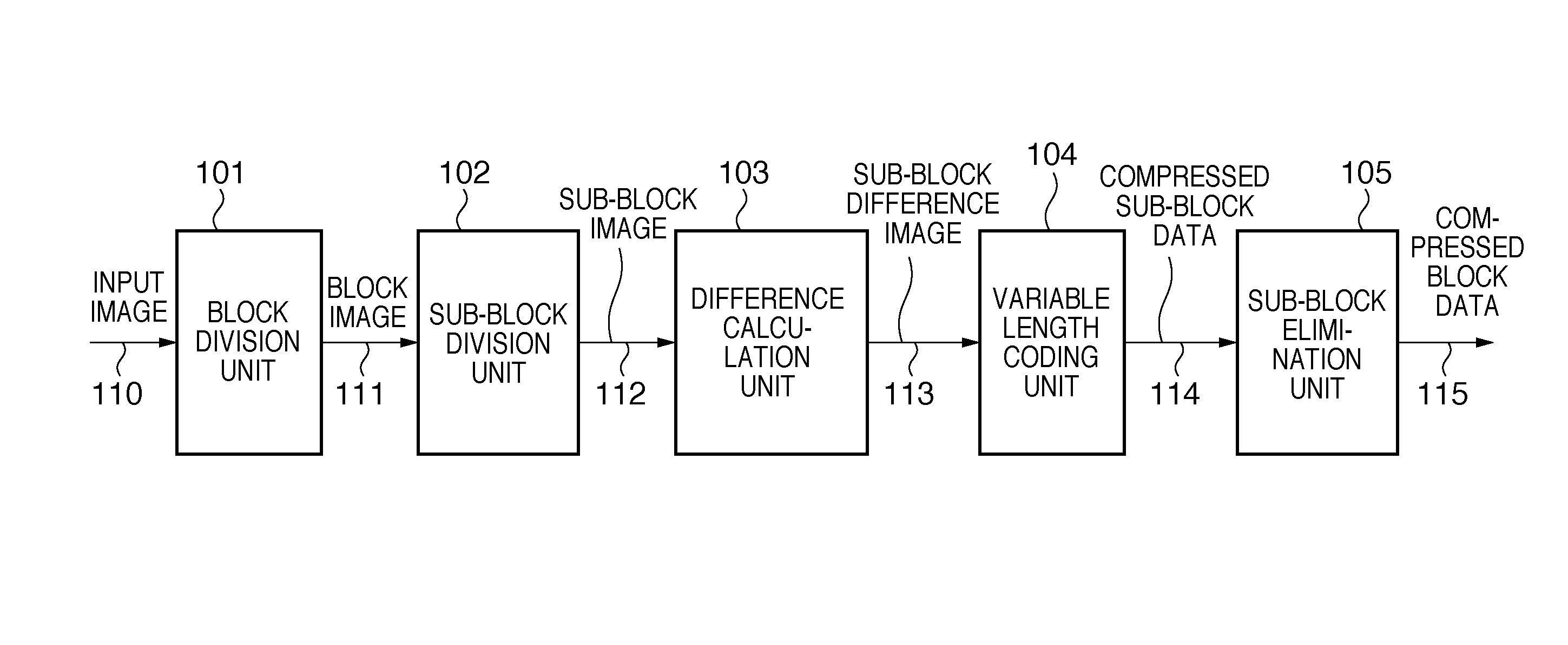
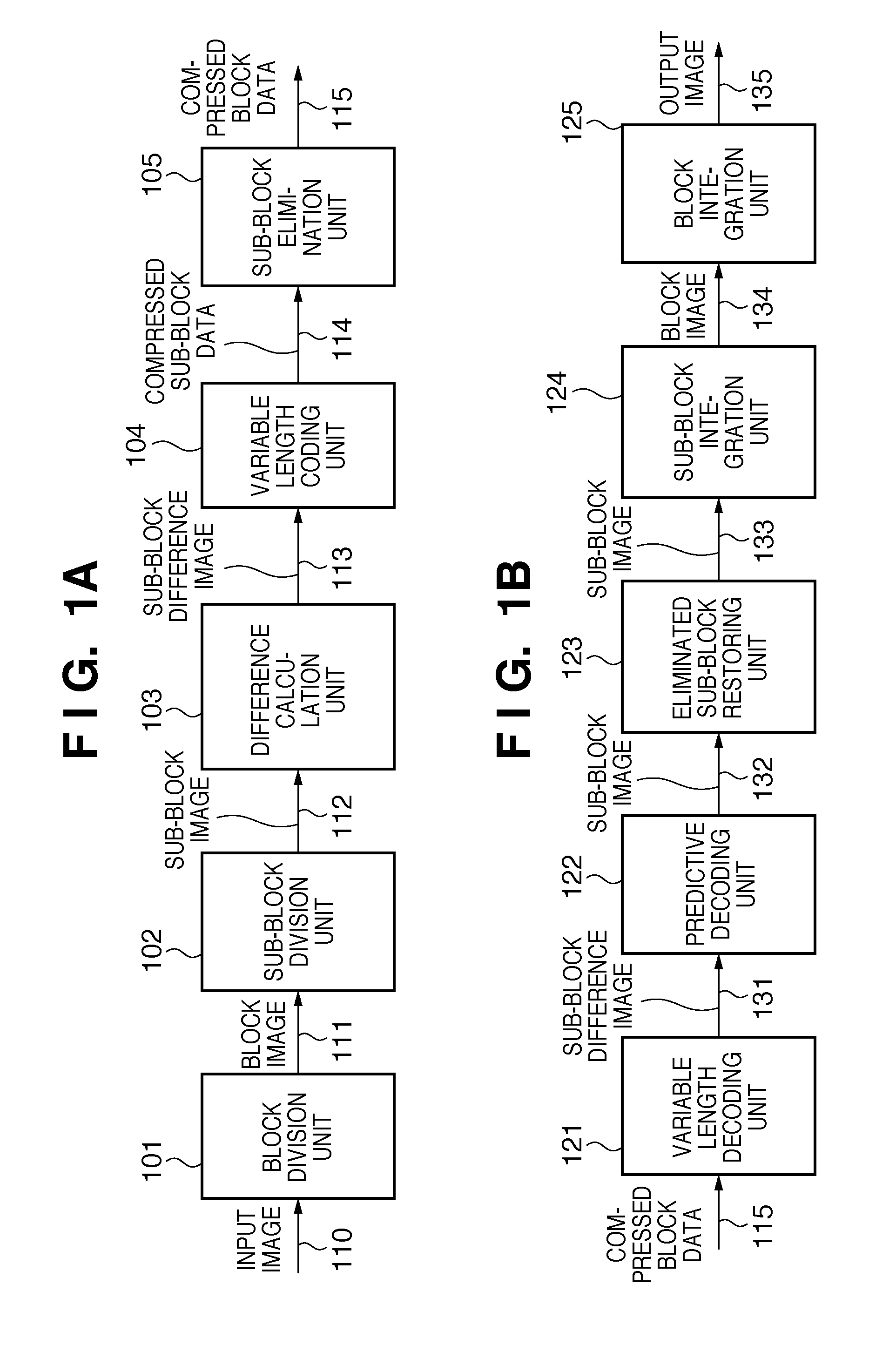
[0048]FIG. 1A is a block diagram of the arrangement of an image encoding apparatus in the first embodiment. FIG. 1B is a block diagram of the arrangement of an image decoding apparatus.

[0049]The image encoding apparatus comprises a block division unit 101, sub-block division unit 102, difference calculation unit 103, variable length coding unit 104, and sub-block elimination unit 105. The image decoding apparatus comprises a variable length decoding unit 121, predictive decoding unit 122, eliminated sub-block restoring unit 123, sub-block integration unit 124, and block integration unit 125.

[0050]The image encoding apparatus will be explained first.

[0051]The block division unit 101 receives image data to be encoded via a signal line 110 for each block made up of a plurality of pixels. The block division unit 101 outputs the received block image to the sub-block division unit 102 via a signal line 111. Image data of a block will be simply referred to as a block image or block image d...

second embodiment

[0094]FIG. 7A is a block diagram of the arrangement of an image encoding apparatus in the second embodiment. FIG. 7B is a block diagram of the arrangement of an image decoding apparatus. The image encoding apparatus and image decoding apparatus in the second embodiment will become apparent from the following description, and are particularly suitable for a character-line image.

[0095]The image encoding apparatus in the second embodiment comprises a blocking unit 701, two-color extracting unit 702, identification information generating unit 703, encoding unit 704, and packing unit 705. The image decoding apparatus comprises an unpacking unit 711, registers 712 and 713, a decoding unit 714, a selector 715, and a rasterization unit 716. Buffer memories are interposed between the respective processing units in order to establish synchronization, but are not shown in FIG. 7A.

[0096]The image encoding apparatus in the second embodiment will be explained first. Also in the second embodiment,...

fifth embodiments

Third to Fifth Embodiments

[0127]The third to fifth embodiments according to the present invention will be described with reference to the accompanying drawings. Image data to be encoded in the following embodiments is binary image data. Note that the binary image is not only an image in which, for example, pixel values are 0 and 1. The embodiments can also be applied to even a case where, for example, the appearance densities of 8-bit pixel values are two, 50 and 150.


PUM


Abstract

This invention scans a block using a window having a size of p×q pixels, and encodes p×q sub-block data each formed from pixel data at relatively identical positions in windows. A blocking unit receives a 16×16-pixel block image. A sub-block division unit scans the received block for each 2×2-pixel window, and generates 2×2 sub-block data each having a size of 8×8 pixels. Each sub-block is formed from pixel data at relatively identical positions in windows. A variable length coding unit encodes each sub-block data. When the sum of encoded sub-block data exceeds an allowable encoded data amount, a sub-block elimination unit eliminates encoded sub-block data until the sum becomes equal to or smaller than the allowable encoded data amount. The sub-block elimination unit outputs the remaining encoded sub-block data as encoded data of a block of interest.

Description

BACKGROUND OF THE INVENTION[0001]1. Field of the Invention[0002]The present invention relates to a technique of encoding and decoding an image.[0003]2. Description of the Related Art[0004]One of generally known compression encoding techniques is JPEG. JPEG divides image data to be encoded into blocks each made up of a plurality of pixels, and performs DCT, quantization, and entropy coding for each block. In the series of processes, a quantization step value used in the quantization process is particularly an important parameter which determines the amount of code. When the quantization step value is set large, the DCT coefficient value becomes 0 or almost 0, increasing the compression ratio. The larger the quantization step value becomes, the larger the difference from an original image before encoding becomes. This appears as degradation of the image quality.[0005]As a technique of increasing the coding efficiency while preventing degradation of the image quality, Japanese Patent L...

Claims


Application Information

Patent Timeline
Patent Type & Authority Patents(United States)
IPC IPC(8): H04B1/66
CPCH04N19/176H04N19/70H04N19/169H04N19/60H04N19/587H04N19/132H04N19/146H04N19/154H04N19/593H04N19/91
Inventor HASHIGUCHI, NORIYASUISHIKAWA, HISASHIHOSAKI, KENTA
Owner CANON KK
Why Eureka
Try Eureka