
Speech decoding apparatus and speech encoding apparatus

a speech encoding and speech encoding technology, applied in the field of speech encoding apparatus and speech encoding apparatus, can solve the problems of speech encoding efficiency, speech encoding efficiency degradation, and ineffective concealment processing of preceding frame information, so as to improve the efficiency of speech encoding

Active Publication Date: 2009-12-31
III HLDG 12 LLC
View PDF7 Cites 34 Cited by
  • Summary
  • Abstract
  • Description
  • Claims
  • Application Information

AI Technical Summary

Benefits of technology

The present invention relates to a speech decoding apparatus and speech encoding apparatus that can effectively conceal lost frames in speech signals. This is important for high-quality speech decoding in VoIP applications, where frame loss is common. The invention uses a lost frame concealment method that reduces the amount of relevant information transmitted in past or future frames, resulting in improved speech encoding efficiency. The invention also includes a pitch pulse detection method and an excitation signal compensation section for improved speech decoding and speech encoding, respectively. Overall, the invention enables effective speech decoding and encoding even in cases where preceding frames are lost.

Problems solved by technology

In the case of CELP speech codecs, there are many cases in which quality degradation due to frame loss in a speech onset portion is a problem.
The reason for this may be that signal variation is great and correlativity with the signal of the preceding frame is low in the onset portion, and therefore concealment processing using preceding frame information does not function effectively.
Alternatively, the reason may be that in a frame of a subsequent voiced portion, an excitation signal encoded in the onset portion is actively used as an adaptive codebook, and therefore the effects of loss of an onset portion are transmitted to a subsequent voiced frame, tending to cause major distortion of a decoded speech signal.

Method used


Image

  • Speech decoding apparatus and speech encoding apparatus
  • Speech decoding apparatus and speech encoding apparatus
  • Speech decoding apparatus and speech encoding apparatus

Examples


embodiment 1

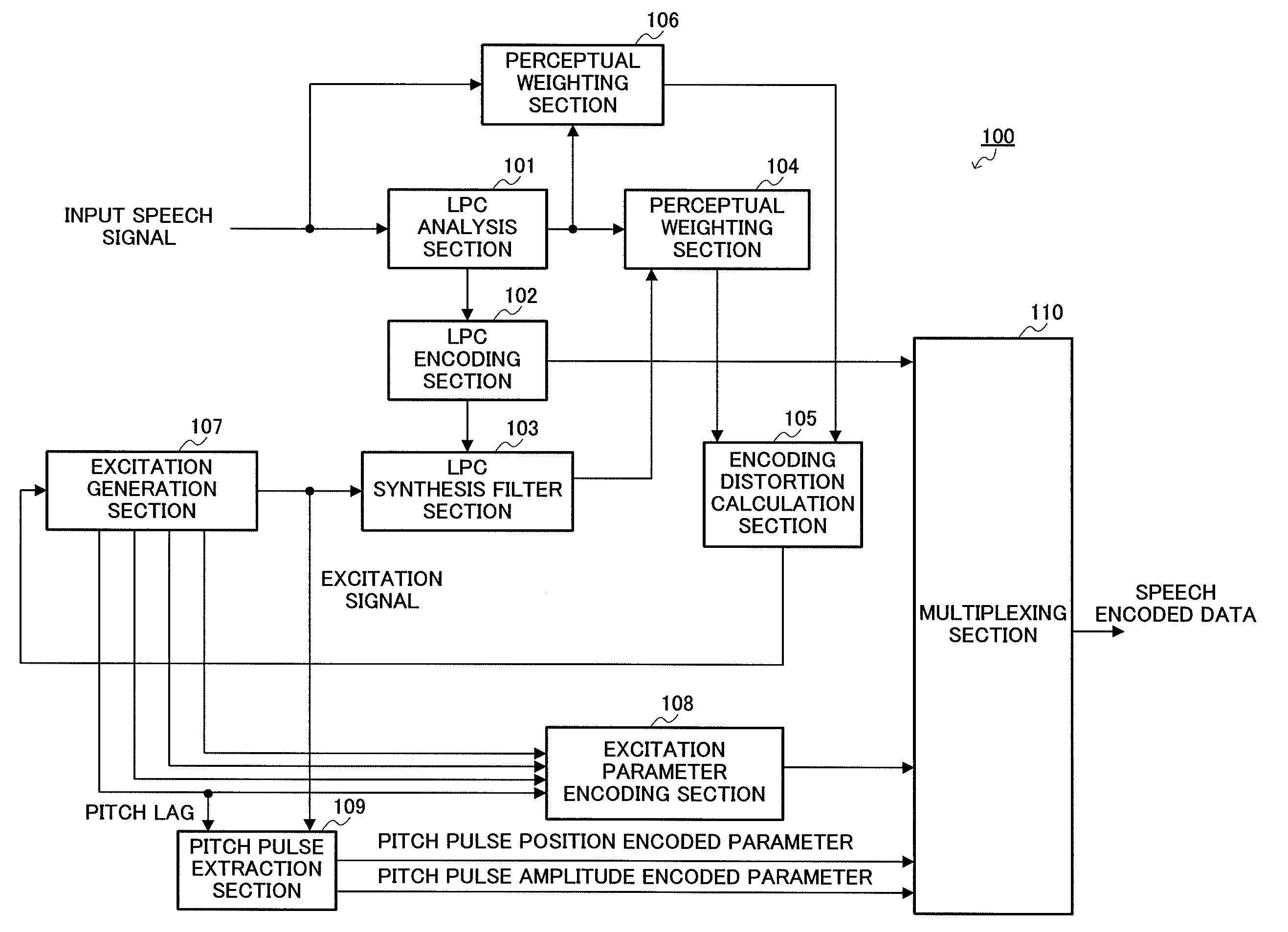
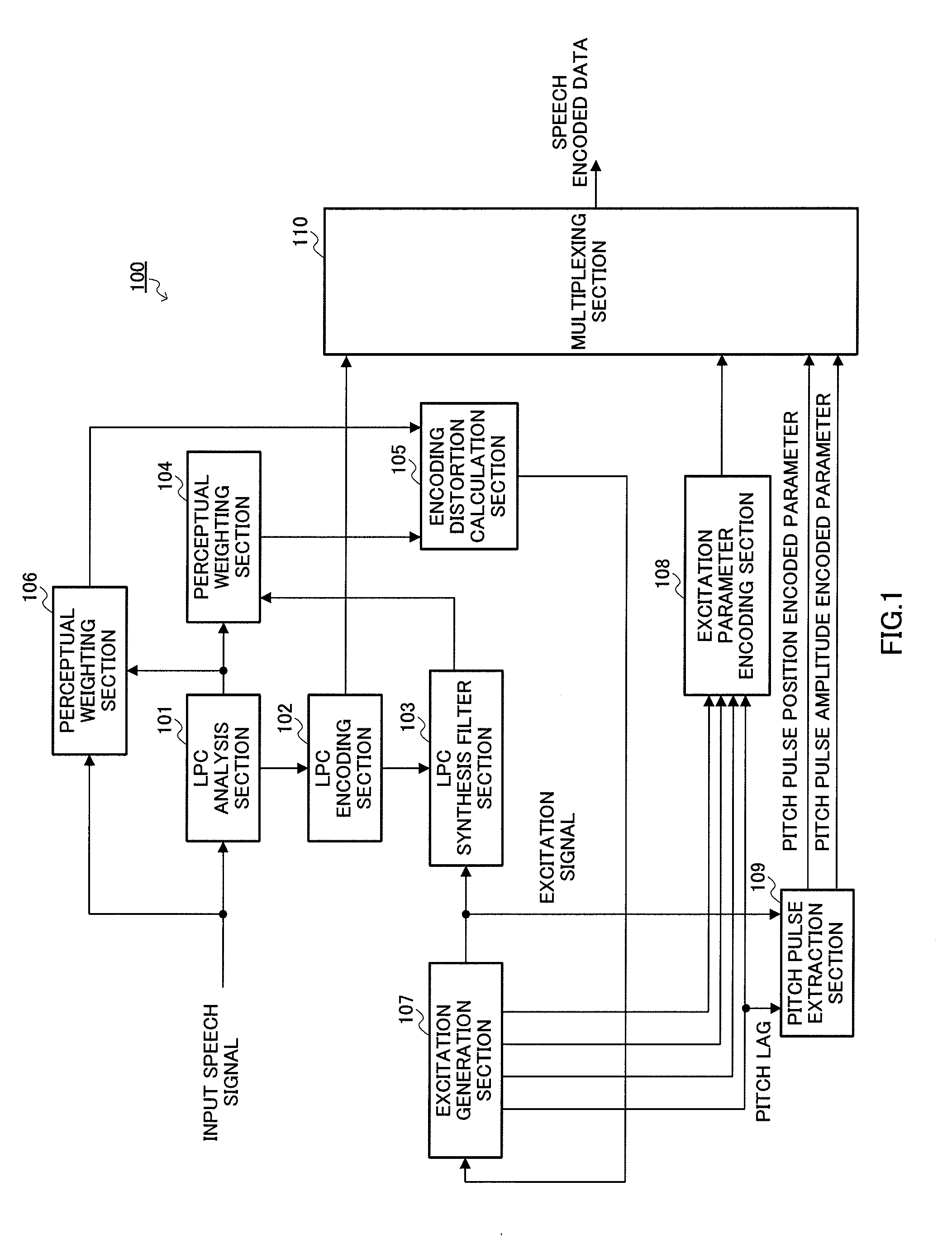
[0046]FIG. 1 is a block diagram showing the main configuration of speech encoding apparatus 100 according to Embodiment 1 of the present invention. Here, a CELP speech encoding apparatus is shown as speech encoding apparatus 100 by way of example.

[0047]Speech encoding apparatus 100 is equipped with LPC analysis section 101, LPC encoding section 102, LPC synthesis filter section 103, perceptual weighting section 104, encoding distortion calculation section 105, perceptual weighting section 106, excitation generation section 107, excitation parameter encoding section 108, pitch pulse extraction section 109, and multiplexing section 110.

[0048]The sections of speech encoding apparatus 100 perform the following operations. Encoding processing in speech encoding apparatus 100 is performed in frame units.

[0049]LPC analysis section 101 performs linear predictive analysis (LPC analysis) on an input speech signal, and outputs an obtained LPC coefficient to LPC encoding section 102, perceptual...

embodiment 2

[0101]Generally, if the power of a decoded excitation signal obtained by performing lost frame concealment processing in a speech decoding apparatus differs greatly from the power of an input speech signal subject to encoding by a speech encoding apparatus, subjective degradation occurs in the decoded speech signal. Therefore, it is necessary for decoded speech signal power to be adjusted in a speech decoding apparatus so as to match the power of a speech encoding apparatus input speech signal. In Embodiment 2 of the present invention, a match between speech encoding apparatus input speech signal amplitude and decoded speech signal amplitude is maintained while adjusting decoded speech signal power.

[0102]FIG. 8 is a block diagram showing the main configuration of speech encoding apparatus 300 according to Embodiment 2 of the present invention. Speech encoding apparatus 300 has the same kind of basic configuration as speech encoding apparatus 100 according to Embodiment 1 (see FIG. 1...

embodiment 3

[0122]First, a decoded excitation signal obtained if an aperiodic peak waveform happens to be present in an excitation signal to be encoded and lost frame concealment processing is performed by means of CELP encoding is shown in FIG. 12.

[0123]FIG. 12A is a drawing showing the waveform of an excitation signal subject to encoding by a CELP speech encoding apparatus. As shown in FIG. 12A, the excitation signal of frame m−1 does not have periodicity, and an aperiodic peak waveform—such as a plosive consonant or sudden noise, for example—is present at position FP0. FIG. 12B shows the waveform of a decoded excitation signal obtained by a CELP speech decoding apparatus performing decoding and lost frame concealment processing on the excitation signal shown in FIG. 12A when frame m is lost. FIG. 12B illustrates a case in which frame m is lost. As shown in FIG. 12B, new pitch periodicity that was not present in the excitation signal waveform shown in FIG. 12A appears in the frame m decoded e...


PUM


Abstract

Provided is an audio decoding device capable of suppressing an information amount for a lost frame compensation process and encoding efficiency. In this device, a decoded sound source generation unit (203) generates a lost frame decoded sound source signal; a pitch pulse information decoding unit (204) decodes the pitch pulse position information and the pitch pulse amplitude information; a pitch pulse waveform learning unit (205) learns a pitch pulse learning waveform in the past frame in advance from the lost frame; a convolution unit (206) amplitude-adjusts the pitch pulse learning waveform according to the pitch pulse amplitude information, and convolutes the pitch pulse waveform into a time axis which has been amplitude-adjusted according to the pitch pulse position information; a sound source signal correction unit (207) adds or replaces the pitch pulse waveform convoluted into the time axis to the lost frame decoded sound source signal.

Description

TECHNICAL FIELD[0001]The present invention relates to a speech decoding apparatus and speech encoding apparatus, and chiefly relates to a lost frame concealment method in these apparatuses.BACKGROUND ART[0002]A speech codec for VoIP (Voice over IP) use is required to have high packet loss tolerance. It is desirable for a next-generation VoIP codec to achieve error-free quality even at a comparatively high frame loss rate (for example, 6%).[0003]In the case of CELP speech codecs, there are many cases in which quality degradation due to frame loss in a speech onset portion is a problem. The reason for this may be that signal variation is great and correlativity with the signal of the preceding frame is low in the onset portion, and therefore concealment processing using preceding frame information does not function effectively. Alternatively, the reason may be that in a frame of a subsequent voiced portion, an excitation signal encoded in the onset portion is actively used as an adapt...

Claims


Application Information

Patent Timeline
Patent Type & Authority Applications(United States)
IPC IPC(8): G10L11/04G10L19/00G10L19/005G10L19/09G10L25/90
CPCG10L19/005G10L25/90H04L47/10G10L2019/0011H04L47/43
Inventor KAWASHIMA, TAKUYAEHARA, HIROYUKIYOSHIDA, KOJI
Owner III HLDG 12 LLC
Learn More