Bi-Wing Arm Support System

a technology of biceps and support systems, applied in the field of medical devices, can solve the problems of significant ergonomic safety and injury risk, failure of routine movement and methodologies for moving patients on the surgical table pad based system, and the healthcare industry faces a lack of products

Pending Publication Date: 2022-01-06
GOMEZ DAVID J
View PDF5 Cites 1 Cited by
  • Summary
  • Abstract
  • Description
  • Claims
  • Application Information

AI Technical Summary

Problems solved by technology

Routine movement and methodologies for moving patients on pad based systems for surgical tables begin to fail, especially during the care of moderate to morbidly obese patients.
Rising obesity rates in the United States also place significant ergonomic safety and injury risk to healthcare providers as they must routinely physically lift and move these patients in order to facilitate surgical procedures.
The healthcare industry faces a problem with a lack of products focused on improving methodologies and practices that facilitate less variance and safe care strategies, i.e., process improvements required for surgical positioning.
The industry also lacks products designed to provide safer and more ergonomic processes for moving patients, which can be a key contributor to musculoskeletal disorders (MSD) and injuries (especially involving the back) suffered by providers.

Method used


Image

  • Bi-Wing Arm Support System
  • Bi-Wing Arm Support System
  • Bi-Wing Arm Support System

Examples


Embodiment Construction

[0032]At the outset, it should be clearly understood that like reference numerals are intended to identify the same structural elements, portions or surfaces consistently throughout the several drawing figures, as such elements, portions or surfaces may be further described or explained by the entire written specification, of which this detailed description is an integral part. Unless otherwise indicated, the drawings are intended to be read (e.g., cross-hatching, arrangement of parts, proportion, debris, etc.) together with the specification, and are to be considered a portion of the entire written description of this invention. As used in the following description, the terms “horizontal”, “vertical”, “left”, “right”, “up” and “down”, as well as adjectival and adverbial derivatives thereof, (e.g., “horizontally”, “rightwardly”, “upwardly”, etc.), simply refer to the orientation of the illustrated structure as the particular drawing figure faces the reader. Similarly, the terms “inw...


PUM


Abstract

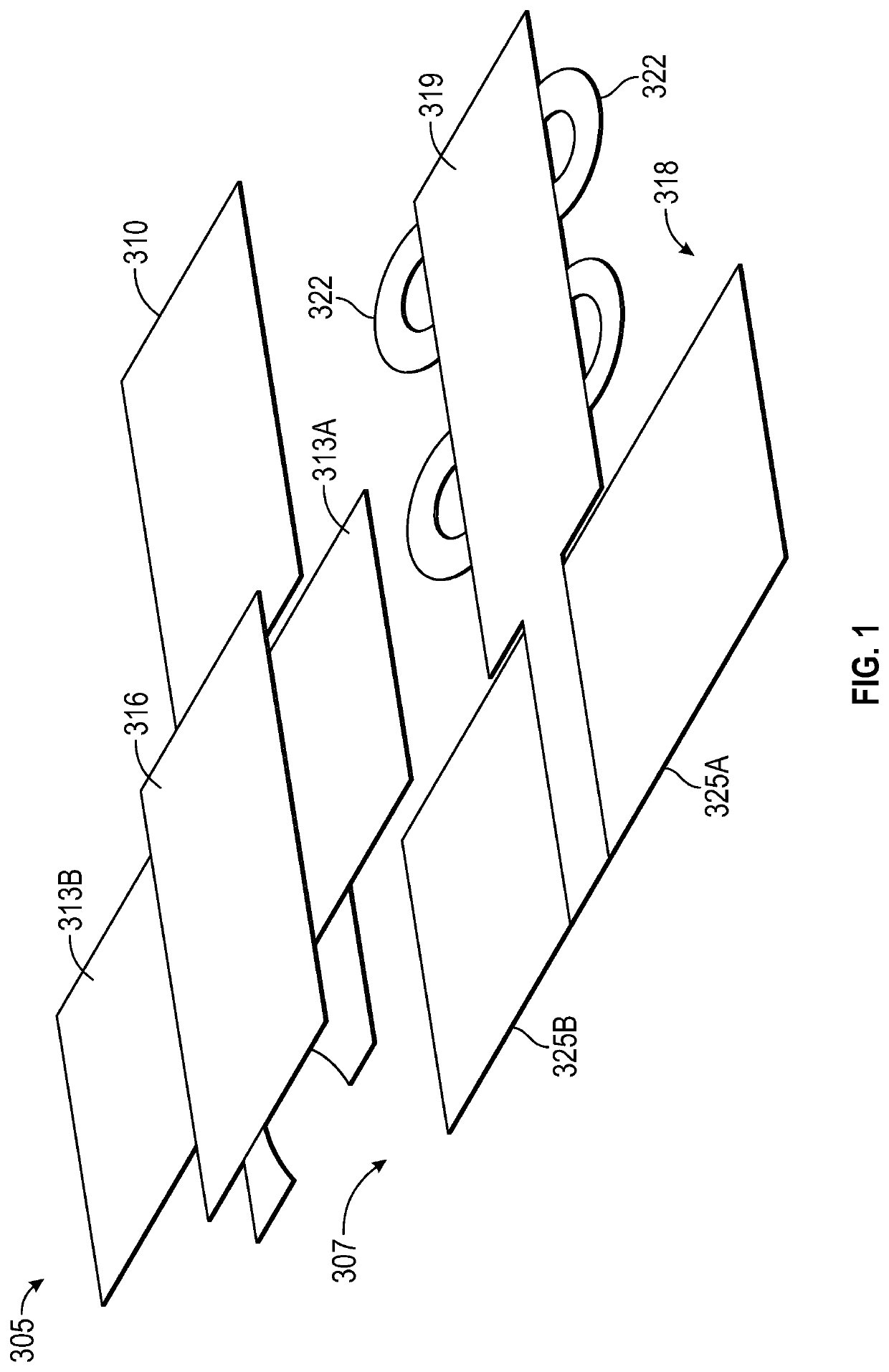
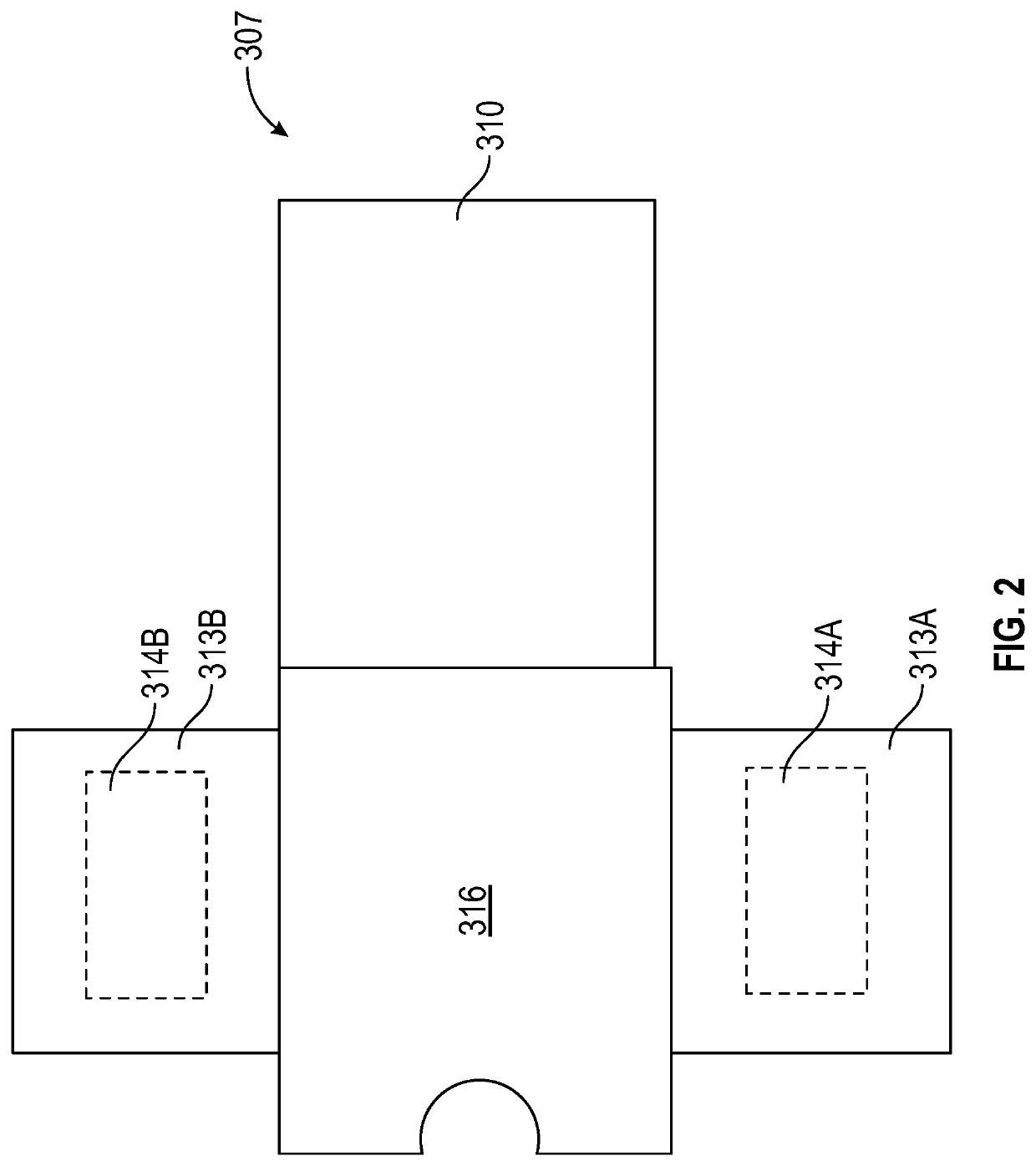
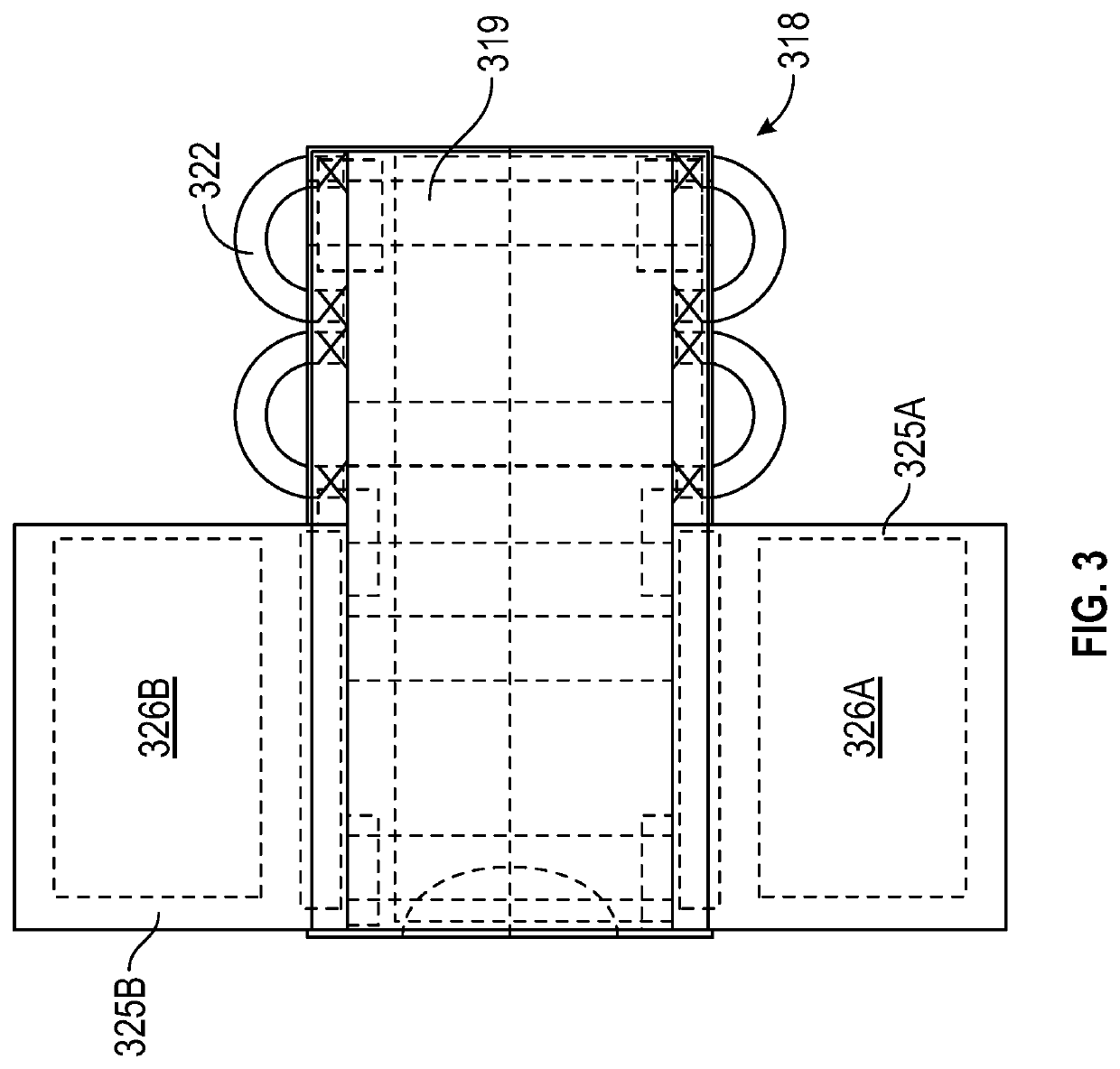
An apparatus for moving a patient on a pad and holding the pad in place on a surgical table. An upper member and a lower member having wings extending from opposite sides are configured and arranged to secure the position of the arms. In this position the arm has been securely wrapped without use of the patient's body weight, and the arm can be easily unwrapped by reversing the steps above, without the necessity of repositioning the patient (to get their body weight off of the device or a draw sheet), for access to the arm during the surgical procedure. Access may be necessary for anesthesia monitoring lines, invasive arterial lines, non-invasive blood pressure cuffs, SPO2 finger probes, and intravenous lines needed for medications and fluid delivery.

Description

CROSS-REFERENCE TO RELATED APPLICATION[0001]The present application is a continuation-in-part patent application that claims priority benefit of U.S. patent application Ser. No. 16 / 964,567 which is a national stage entry of PCT / US2019 / 016005 which has an international filing date of Jan. 31, 2019, which claims priority benefit of U.S. Provisional Patent Application No. 62 / 624,357 filed on Jan. 31, 2018, and entitled “Bi-Wing Arm Support System,” and the present application also claims priority benefit of U.S. Provisional Patent Application No. 63 / 051,406 filed Jul. 14, 2020, and entitled “Bi-Wing Arm Support System,” all of which are hereby incorporated by reference.FIELD OF THE INVENTION[0002]The present invention relates generally to the field of medical devices for use in the surgical theater, and more particularly to an apparatus and method for securing a patient on a surgical table and for moving a patient from one position to another position on the surgical table.BACKGROUND A...

Claims


Application Information

Patent Timeline
Patent Type & Authority Applications(United States)
IPC IPC(8): A61G7/10A61F5/37A61G13/12
CPCA61G7/1092A61G7/1023A61G13/1235A61F5/3723A61G7/1026
Inventor GOMEZ, DAVID J.
Owner GOMEZ DAVID J
Why Eureka
Try Eureka