Wireless Controlled Airplane and Arithmetic Processing Device

a technology of arithmetic processing and a controlled airplane, which is applied in the field of wireless controlled airplanes, can solve the problems of difficult control and difficulty in course adjustment of a straight flight, and achieve the effects of eliminating unnatural behaviors, enhancing pose control, and facilitating control

Pending Publication Date: 2022-04-21
FUTABA CORPORATION
View PDF0 Cites 0 Cited by
  • Summary
  • Abstract
  • Description
  • Claims
  • Application Information

AI Technical Summary

Benefits of technology

[0011]The wireless controlled airplane or arithmetic processing device according to the present invention is provided so that when the second or third actuator has been operated while performing the PID control for the first actuator, the integra

Problems solved by technology

However, PID control may render the flight behavior unnatural which makes the control difficult.
For example, when performing the PID control for the rudder, a course adjustment of a straight flight may b

Method used


Image

  • Wireless Controlled Airplane and Arithmetic Processing Device
  • Wireless Controlled Airplane and Arithmetic Processing Device
  • Wireless Controlled Airplane and Arithmetic Processing Device

Examples


first embodiment

3. First Embodiment

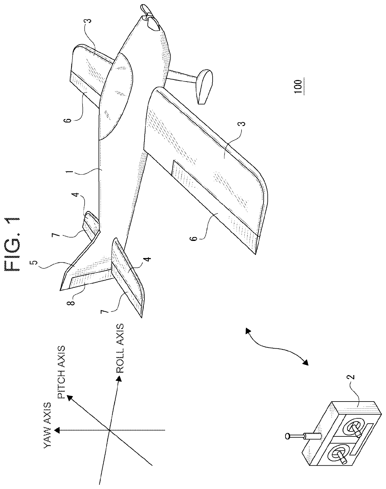
[0034]As a first embodiment, a configuration will be described in which a first actuator control section for a first actuator reduces an integral element of the PID control depending on an operation signal for the second / third actuator control section.

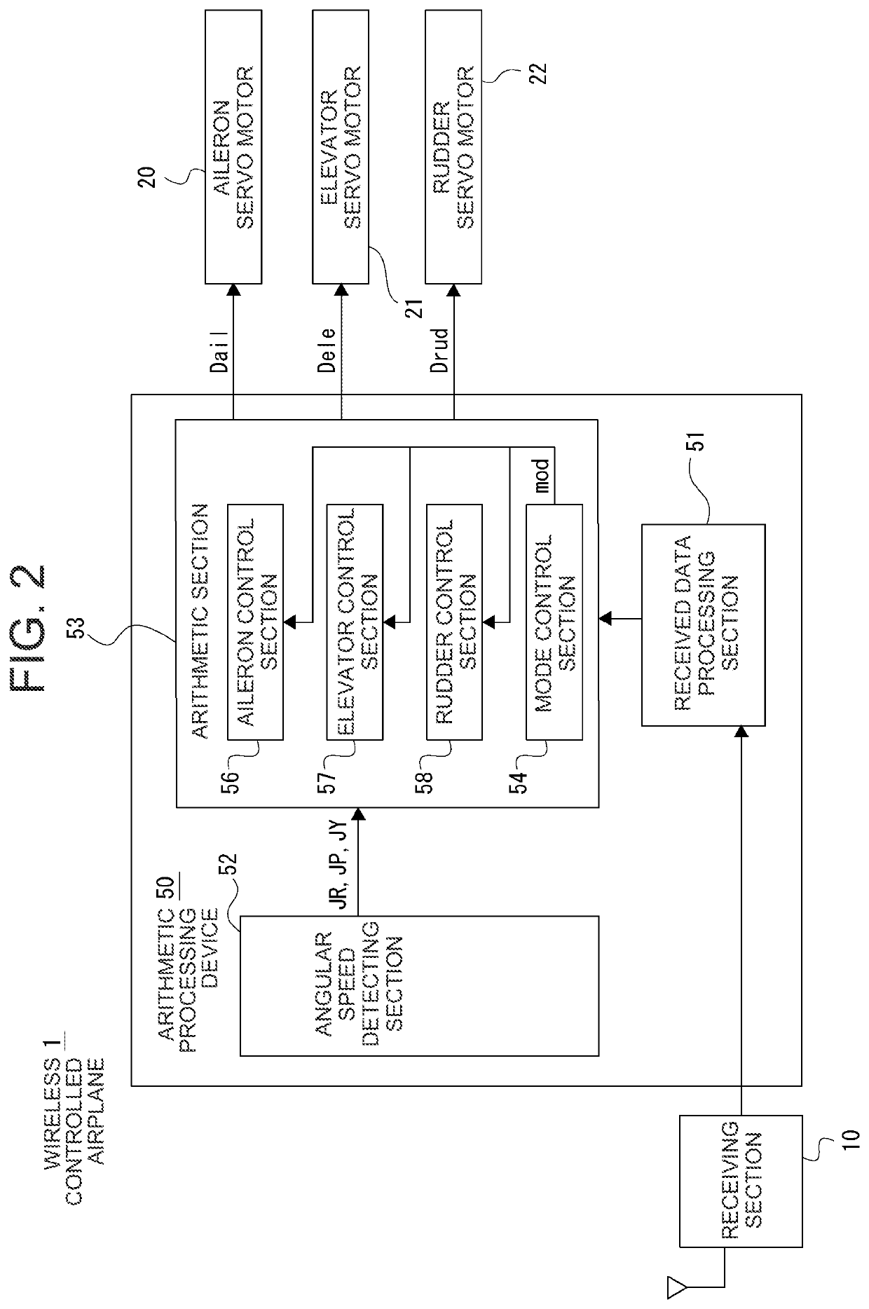
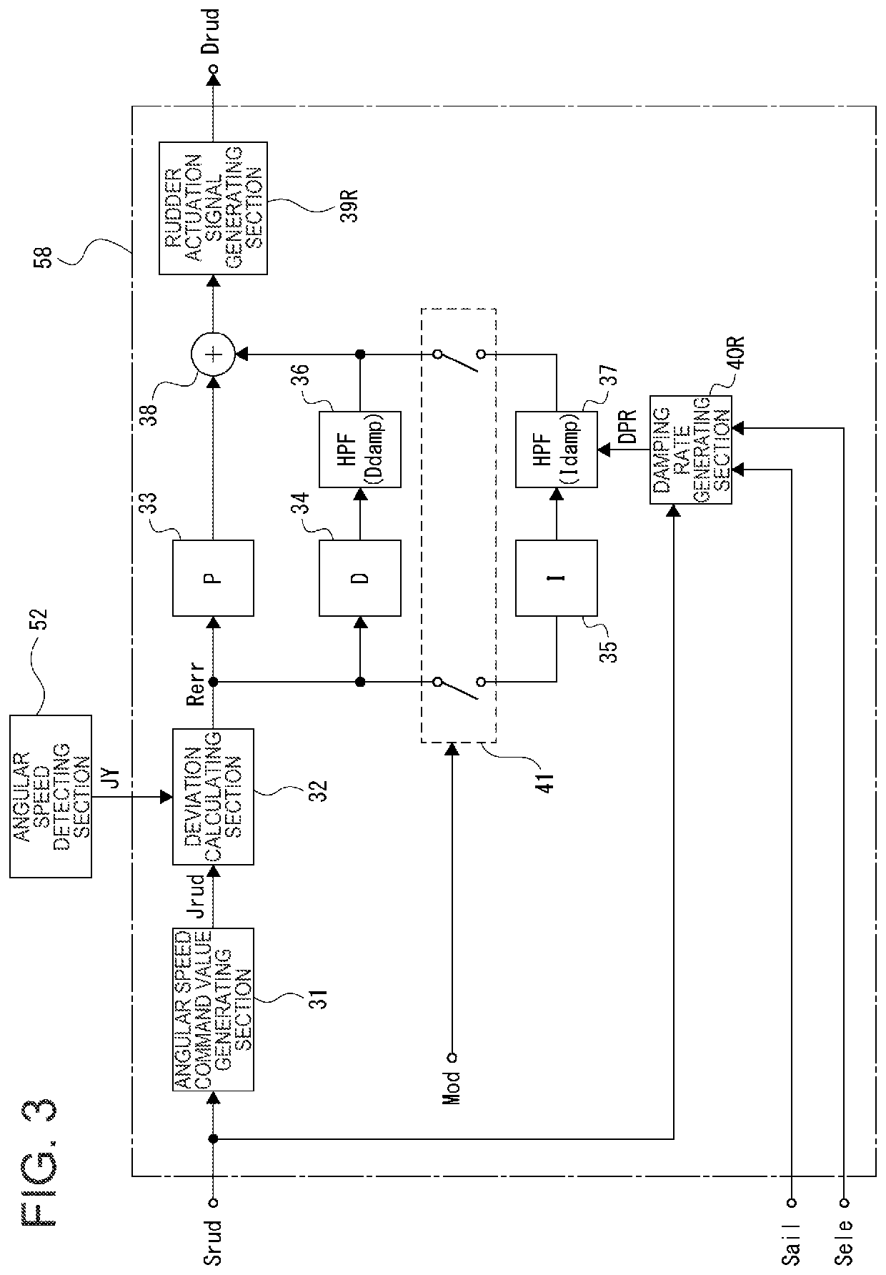
[0035]FIG. 3 shows the rudder control section 58 as an example for the first actuator control section. This means that FIG. 3 assumes that the rudder servo motor 22 is the first actuator. The rudder control section 58 includes an angular speed command value generating section 31, a deviation calculating section 32, a P-control calculating section 33, a D-control calculating section 34, an I-control calculating section 35, HPFs (high pass filters) 36 and 37, a combination section 38, a rudder actuation signal generating section 39R, a damping rate generating section 40R, and a mode switch 41.

[0036]The control device 2 transmits a rudder operation signal Srud which is demodulated in the receiving section 10 and decoded...

second embodiment

4. Second Embodiment

[0064]As a second embodiment, a configuration will be described in which a first actuator control section for a first actuator cuts an integral element of the PID control depending on an operation signal for the second / third actuator control section. FIG. 5 shows the rudder control section 58 as an example for the first actuator control section. The configuration according to FIG. 5 differs from the example according to FIG. 3 in the following points:

[0065]The rudder operation signal Srud is inputted to the damping rate generating section 40R, wherein the damping rate DPR is set depending on the rudder operation amount. This means that the damping rate DPR to be set for the HPF 37 is defined as follows:

DPR=DPR(Srud).

[0066]In the case of FIG.5, the mode switching section 42 for controlling the mode switch 41 is provided. The mode switching section 42 switches the mode switch 41 on / off depending on the mode control signal mod. In addition, the aileron operation sig...


PUM


Abstract

An objective of the present invention is to eliminate unnatural behaviors of a wireless controlled airplane during PID control. In a wireless controlled airplane, a receiving section receives a first operation signal for a first actuator, a second operation signal for a second actuator, and a third operation signal for a third actuator, wherein the first, second and third operation signals are provided as operation signals wirelessly transmitted. A first actuator control section is configured to generate an actuation signal for the first actuator by means of PID control depending on the first operation signal, and to reduce an integral element in the PID control depending on an operation value for the second or third operation signal. Alternatively, the first actuator control section is configured to perform switching to a control without an integral element from the PID control.

Description

CROSS-REFERENCE TO RELATED APPLICATION[0001]This application claims the priority benefit of Japanese Patent Application No. 2020-173974 filed Oct. 15, 2020, which is fully incorporated herein by reference.BACKGROUND OF THE INVENTIONTechnical Field[0002]The present invention relates to technical fields of a wireless controlled airplane configured to be controlled via wireless communication, and of an arithmetic processing device for a wireless controlled airplane.Background Art[0003]For example, wireless controlled airplanes are known which perform a flight via wireless communication based on operation of a control device. Patent Document 1 as listed below discloses a wireless controlled airplane configured to be controlled via wireless communication, wherein the wireless controlled airplane includes an aileron, elevator and rudder configured to be driven to control a pose and / or flight direction of an airframe.CITATION LISTPatent Literature[0004]Patent Document 1: JP 2016-052401 ASU...

Claims


Application Information

Patent Timeline
IPC IPC(8): B64C39/02A63H27/00B64C9/06
CPCB64C39/024A63H27/02B64C9/06B64C2009/005B64C2201/042B64C2201/146B64C2203/00B64C2201/021A63H30/04B64U2201/20B64U10/25B64U20/80
Inventor TANAKA, MASAHIRO
Owner FUTABA CORPORATION
Why Eureka
Try Eureka