Antenna device

a multi-feed antenna and antenna technology, applied in the field of antenna devices, can solve the problems of restrictive space for accommodating multi-feed antennas and negatively affecting wireless communication, and achieve the effects of efficient sending and receiving signals, good application, and extraordinary mechanical properties

Active Publication Date: 2022-05-05
INVENTEC PUDONG TECH CORPOARTION +1
View PDF0 Cites 0 Cited by
  • Summary
  • Abstract
  • Description
  • Claims
  • Application Information

AI Technical Summary

Benefits of technology

[0015]In summary, the antenna device includes a housing and a printed antenna located in the housing, and the housing includes a front glass shell, a rear glass shell, and a metal bracket to protect the printed antenna. Therefore, the antenna device has an extraordinary mechanical property. Moreover, the metal bracket has a designed opening on the side thereof to expose the printed antenna so the printed antenna can avoid being interfered by the housing. Therefore, the printed antenna can efficiently send and receive signal, thus the antenna device can be well applied in specific operating bands.

Problems solved by technology

The space for accommodating the multi-feed antennas is restrictively limited.
Therefore, wireless communication is negatively affected since the antennas and other components mutually interfere and generate unwanted radiational coupling relationships.

Method used


Image

  • Antenna device
  • Antenna device
  • Antenna device

Examples


Embodiment Construction

[0024]Reference will now be made in detail to the present embodiments of the invention, examples of which are illustrated in the accompanying drawings. Wherever possible, the same reference numbers are used in the drawings and the description to refer to the same or like parts.

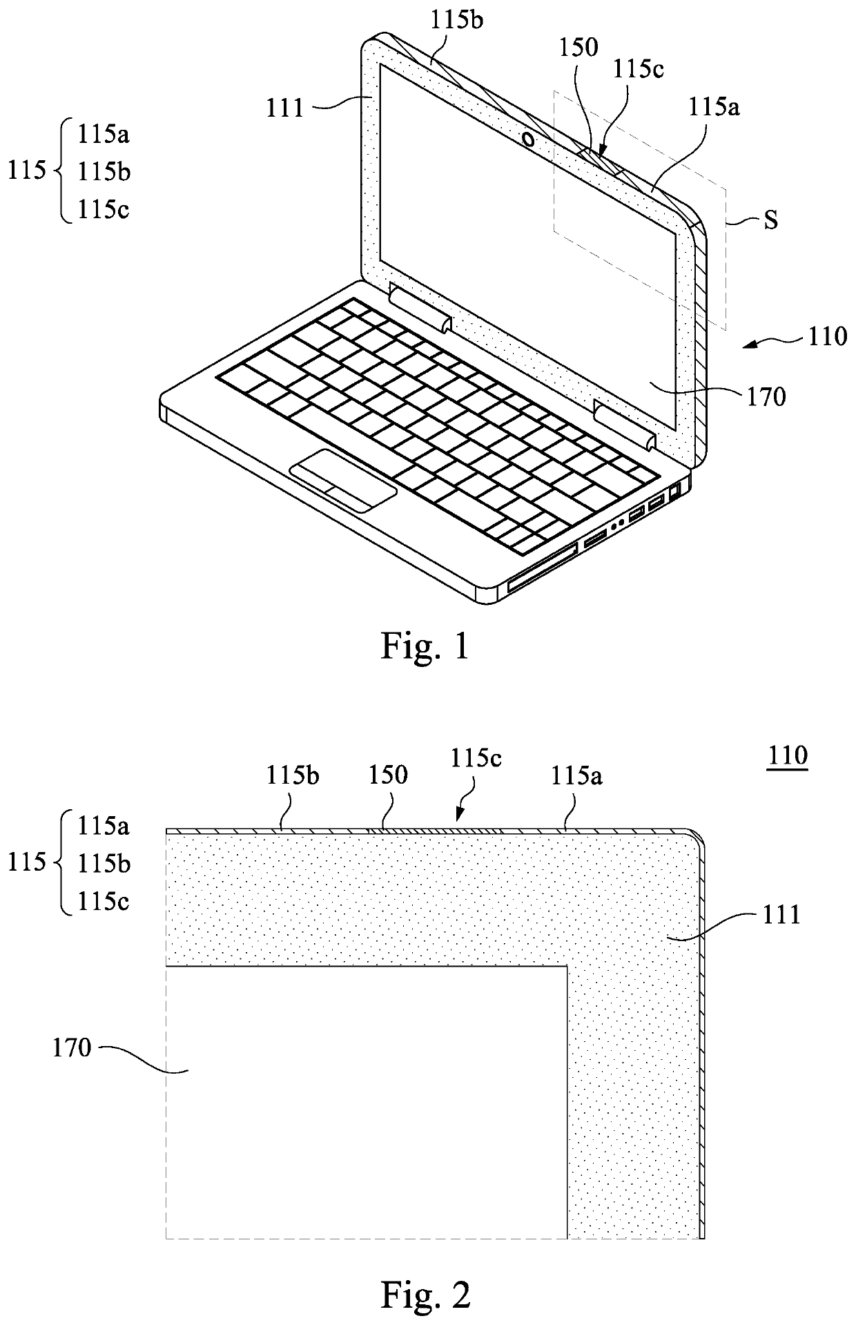
[0025]Reference is made to FIG. 1. FIG. 1 illustrates a schematic view of an antenna device 100 according to some embodiments of the present disclosure in some embodiments of the present disclosure. Specifically, the antenna device 100 is an electric device which can send and receive electromagnetic wave signals. Therefore, the antenna device 100 can be a mobile phone, a computer, or a laptop. For instance, the antenna device 100 includes a display panel 170 to show text, pictures, or videos. The present disclosure is not limited in this respect.

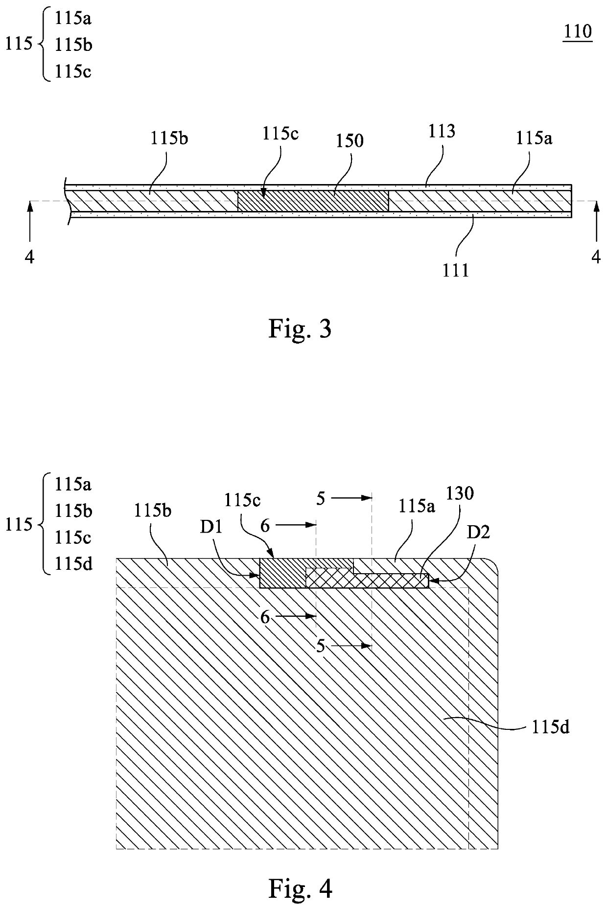
[0026]Reference is made from FIG. 1 to FIG. 4. FIG. 2 illustrates a front view of the dotted square S in FIG. 1. FIG. 3 illustrates a top view of the dotted square S i...


PUM


Abstract

An antenna device includes a housing and a printed antenna. The housing includes a front glass shell, a rear glass shell, and a metal bracket. The metal bracket is between the front glass shell and the rear glass shell, and the metal bracket is connected to outer peripheries of the front glass shell and the rear glass shell to form an accommodation space together. The metal bracket includes a first frame portion, a second frame portion, and an opening, and the opening is defined between the first and second frame portions. The printed antenna is arranged in the housing and between the first and second frame portions, and the opening exposes at least a portion of the printed antenna.

Description

CROSS-REFERENCE TO RELATED APPLICATION[0001]This application claims priority to China Application Serial Number 202011225655.0, filed Nov. 5, 2020, which is herein incorporated by reference in its entirety.BACKGROUNDField of Invention[0002]The present invention relates to antenna devices. More particularly, the present invention relates to printed circuit board (PCB) antenna devices.Description of Related Art[0003]By the characteristics of electromagnetic wave signals through space, wireless communication technology has been widely used for exchanging information, and relative applications have also dramatically grown due to the great range of needs. As wireless communication technology develops, the international standard of the 5th generation (5G) mobile network has recently been established. In comparison with 4th generation (4G) mobile networks, the 5G mobile network has a higher transmission rate, and communication needs in different ranges, such as near field or far field, can...

Claims


Application Information

Patent Timeline
Patent Type & Authority Applications(United States)
IPC IPC(8): H01Q1/42H01Q1/38
CPCH01Q1/421H01Q1/38H01Q1/52H01Q1/42H01Q1/22H01Q1/2258G06F1/1633H01Q1/2266H01Q9/42
Inventor LI, CHIH-CHENG
Owner INVENTEC PUDONG TECH CORPOARTION
Why Eureka
Try Eureka