Eureka AIR delivers breakthrough ideas for toughest innovation challenges, trusted by R&D personnel around the world.

Bone screw

Pending Publication Date: 2022-05-26
VERTISCREW LLC
View PDF0 Cites 0 Cited by
  • Summary
  • Abstract
  • Description
  • Claims
  • Application Information

AI Technical Summary

Benefits of technology

The invention is a bone fixation system that includes an inner receiver, an outer receiver, and a connecting rod. The system allows for unlocked and locked configurations, with the inner receiver being movable longitudinally relative to the outer receiver. The system also includes a screw retainer for securely attaching a bone screw to the outer receiver. The technical effects of this invention include improved stability and secure fixation of bones, as well as a simplified and efficient surgical procedure for bone fixation.

Problems solved by technology

Due to the variation in a patient's anatomy and differences in screw placement technique, screws are often not perfectly aligned which makes securement of a fixation device more difficult.
Frequently, however, this anterior / posterior translation may not be desirable as it may produce suboptimal alignment of the vertebral bodies or even cause fractures of the bone or pullout of the shank portion of the screw from the bone due to the stresses placed on it during the persuading process.
This, however, reduces the bone-screw interface thereby weakening the overall strength of the construct.

Method used


Image

  • Bone screw
  • Bone screw
  • Bone screw

Examples


Embodiment Construction

[0049]Before the subject devices, systems and methods are described, it is to be understood that this invention is not limited to particular embodiments described, as such may, of course, vary. It is also to be understood that the terminology used herein is for the purpose of describing particular embodiments only, and not intended to be limiting, since the scope of the present invention will be limited only by the appended claims.

[0050]Unless defined otherwise, all technical and scientific terms used herein have the same meaning as commonly understood by one of ordinary skill in the art to which this invention belongs.

[0051]It must be noted that as used herein and in the appended claims, the singular forms “a”, “an”, and “the” include plural referents unless the context clearly dictates otherwise. Thus, for example, reference to “a spinal segment” may include a plurality of such spinal segments and reference to “the screw” includes reference to one or more screws and equivalents th...


PUM


Abstract

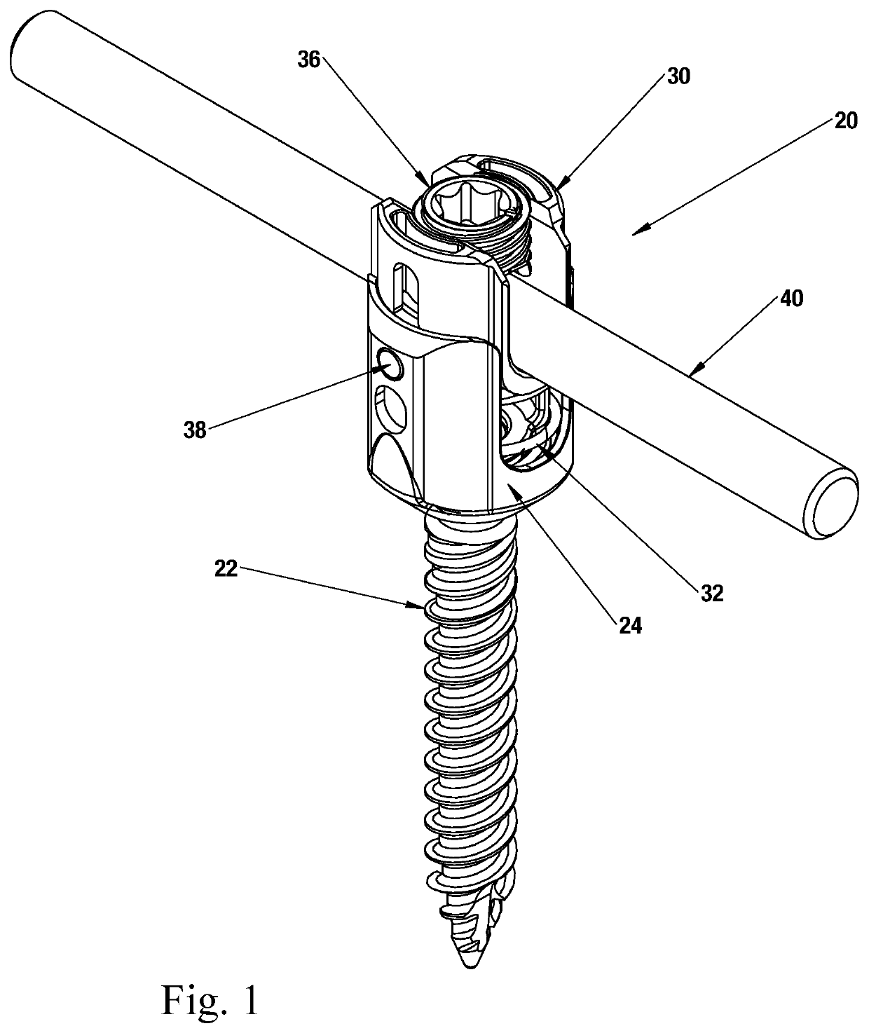
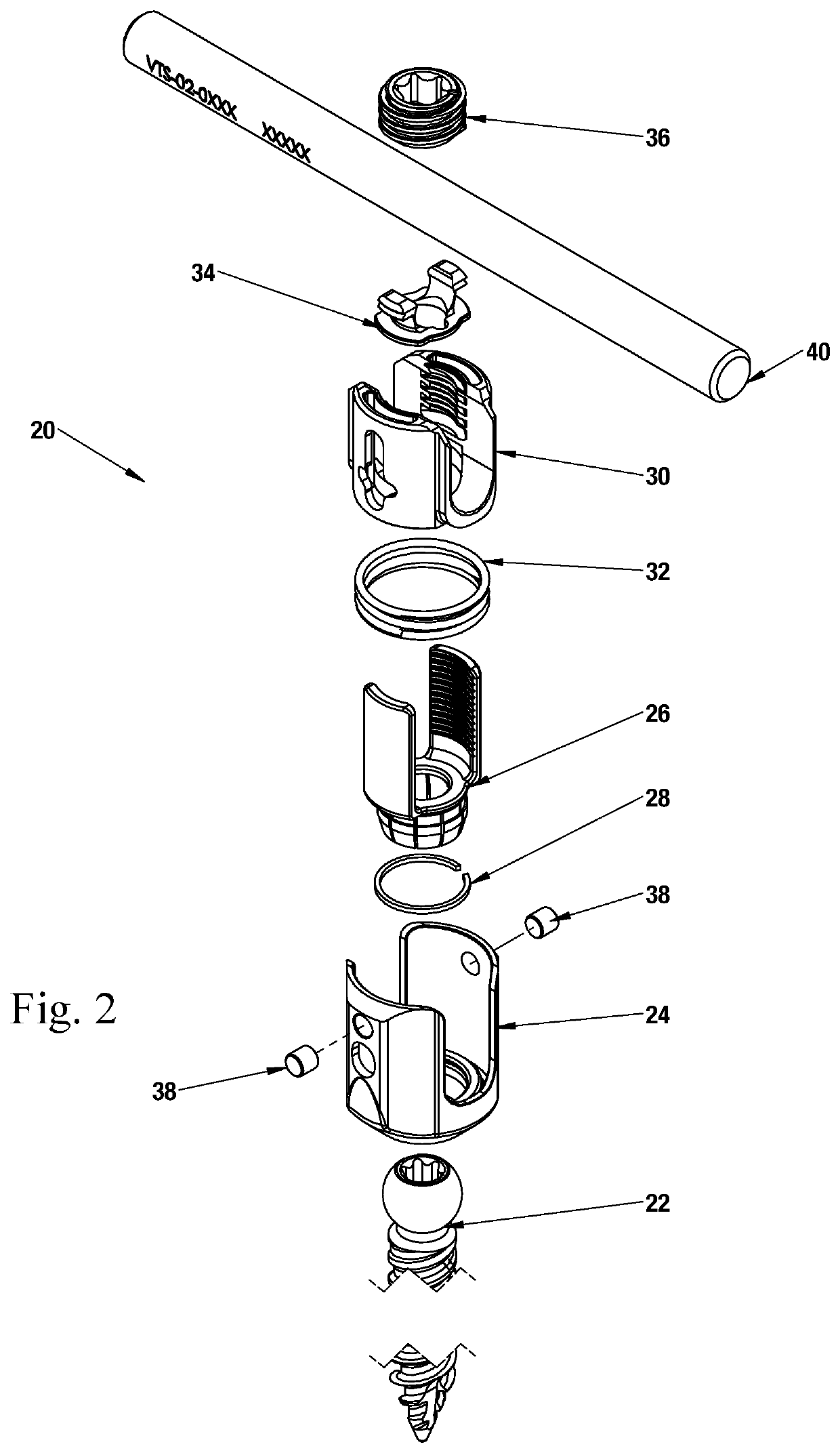
A bone fixation system with variable z-axis translation is provided. The system includes an outer tulip coupled to a bone fastener via a screw retainer. An inner tulip is coupled to the outer tulip such that the inner tulip is longitudinally movably relative to the outer tulip. The inner tulip includes a lock that provides a seat for a connecting rod. The inner tulip together with a seated rod is permitted to translate along the z-axis inside the outer tulip when in an unlocked position. Also in the unlocked position, the bone fastener is free to angulate relative to the outer tulip. The z-axis position of the inner tulip and rod relative to the outer tulip is fixed in a locked position. Also, in the locked position, the bone fastener is locked with respect to the outer tulip. The system may be adjusted between the locked and unlocked positions by way of a set screw.

Description

CROSS-REFERENCE TO RELATED APPLICATIONS[0001]This application is a continuation application of U.S. patent application Ser. No. 15 / 421,822 entitled “Bone screw” filed on Feb. 1, 2017 now U.S. Pat. No. 11,241,258 issued on Feb. 8, 2022 incorporated herein by reference in its entirety which is a continuation application of U.S. patent application Ser. No. 14 / 940,034 entitled “Bone screw” filed on Nov. 12, 2015 now U.S. Pat. No. 9,579,125 issued on Feb. 28, 2017 incorporated herein by reference in its entirety which claims priority to and benefit of U.S. Provisional Patent Application Ser. No. 62 / 078,524 entitled “Bone screw” filed on Nov. 12, 2014 incorporated by reference in its entirety herein, and which is a continuation-in-part of U.S. patent application Ser. No. 14 / 175,058 now U.S. Pat. No. 9,451,991 entitled “Bone screw” filed on Feb. 7, 2014 and issued on Sep. 27, 2016 incorporated by reference in its entirety herein and a continuation-in-part of U.S. patent application Ser. No...

Claims


Application Information

Patent Timeline
IPC IPC(8): A61B17/70A61B17/86A61B17/88
CPCA61B17/7035A61B17/7032A61B17/7037A61B17/8883A61B17/7086A61B17/7091A61B17/862A61B17/7085
Inventor RAJU, MURALIDHARA RUDHRAAKHAVI, AMIR ALIALTARAC, MOTIREGLOS, JOEY
Owner VERTISCREW LLC
Why Eureka
Eureka Blog
Learn More