Camera module, molded photosensitive assembly and manufacturing method thereof, and electronic device

Pending Publication Date: 2022-06-09
NINGBO SUNNY OPOTECH CO LTD
View PDF0 Cites 0 Cited by
  • Summary
  • Abstract
  • Description
  • Claims
  • Application Information

AI Technical Summary

Benefits of technology

The present invention provides a camera module and a molded photosensitive assembly with improved attachment reliability and reduced attachment surface area. This is achieved by elevating the portion of the molded base where the filter member is attached, so as to eliminate the adverse effects of a transition arc surface. The invention also provides a method for manufacturing the camera module and an electronic device using the molded photosensitive assembly. The invention further provides a camera module with a molded reinforcement portion that strengthens the connection strength at the notch between the first and second molded portions, thereby improving the reliability of the camera module.

Problems solved by technology

However, as shown in FIG. 1, limited by the film in the molding process, the corners of the groove 35P in the molded base 32P (i.e., the junction between the portion of the molded base 32P where the filter 33P is attached and the part where the optical lenses 2P is mounted) is not a right angle, but there is a certain transition arc surface 351P, which makes it difficult for the molded base 32P to provide a flat surface for attaching the filter 33P.
However, this will cause the attachment area between the filter 33P and the molded base 32P to become smaller, i.e., a bottom supporting area provided by the molded base 32P for the filter 33P becomes smaller, which would reduce a connection strength between the filter 33P and the molded base 32P, thereby affecting the reliability of the camera module.

Method used


Image

  • Camera module, molded photosensitive assembly and manufacturing method thereof, and electronic device
  • Camera module, molded photosensitive assembly and manufacturing method thereof, and electronic device
  • Camera module, molded photosensitive assembly and manufacturing method thereof, and electronic device

Examples


first embodiment

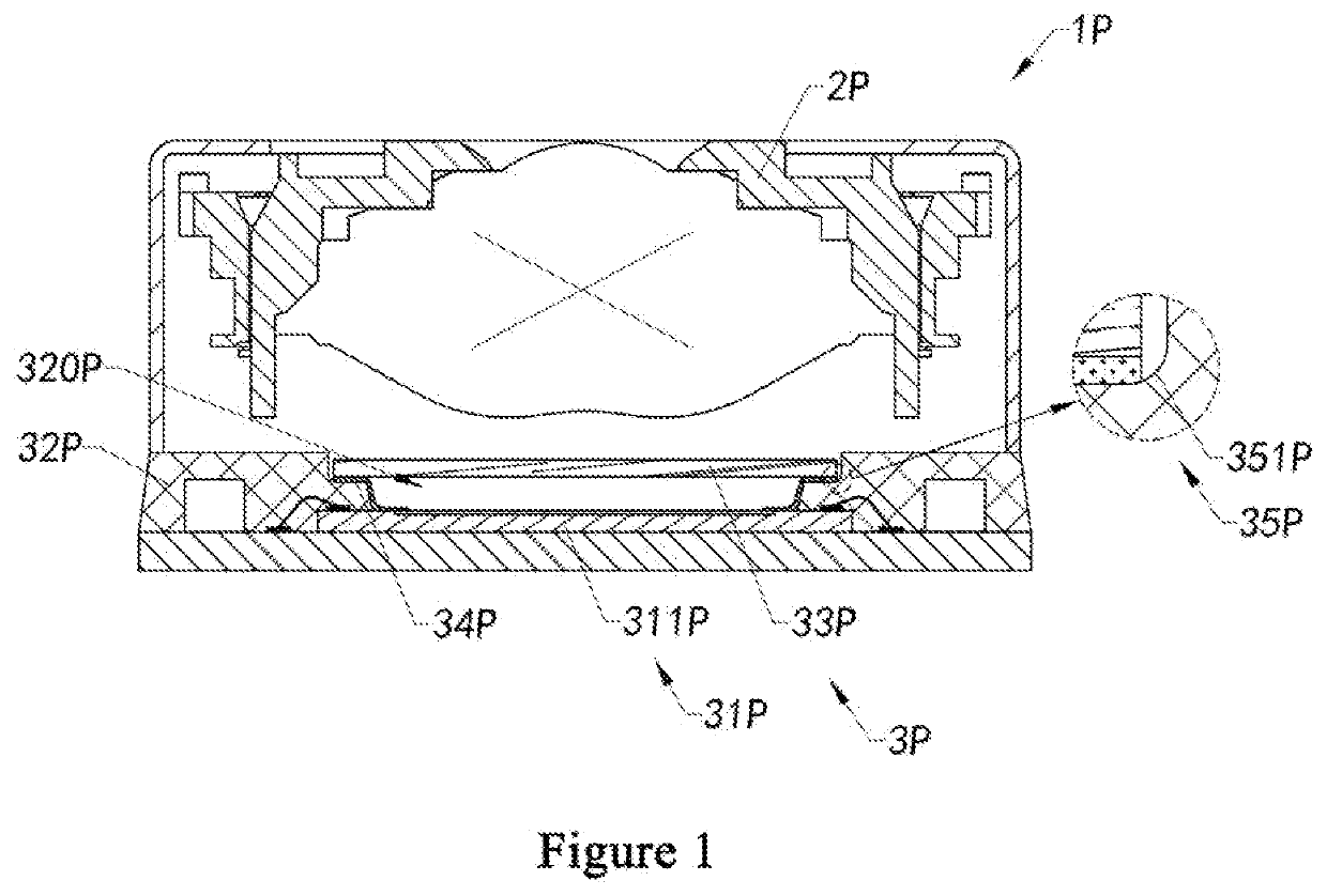
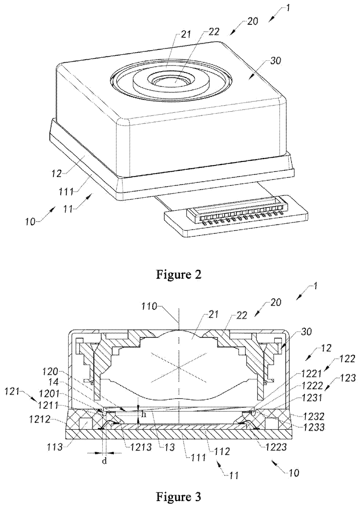
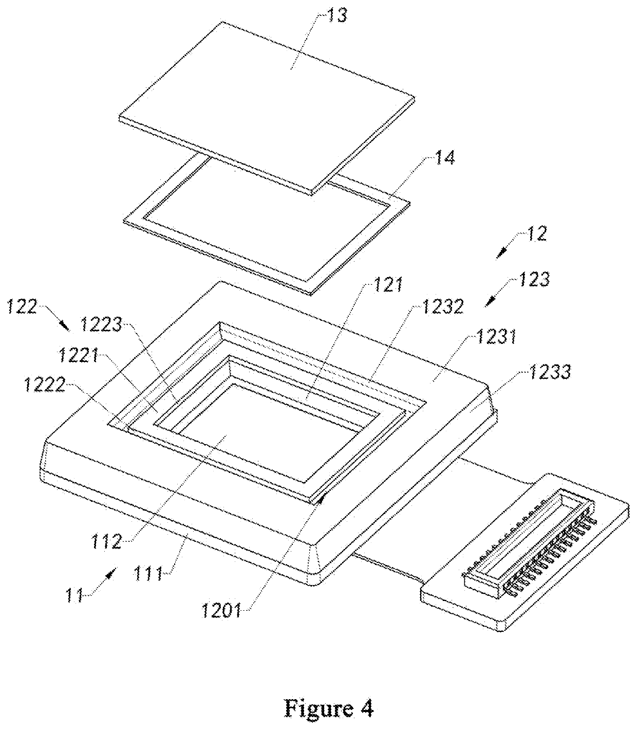
[0112]Therefore, in order to solve the above problems, the present invention provides a camera module, a molded photosensitive assembly and a manufacturing method thereof, so as to eliminate the adverse effects of a transition arc surface generated by coating during a molding process on a filter member. Particularly, as shown in FIGS. 2-4, a camera module 1 according to the present invention is illustrated, wherein the camera module 1 includes a molded photosensitive assembly 10 and at least one optical lenses 20, wherein the molded photosensitive assembly 10 includes an imaging assembly 11, a molded base 12, and a filter member 13, wherein the molded base 12 is molded on the imaging assembly 11, and the filter member 13 is attached to the molded base 12; and the optical lenses 20 is correspondingly disposed on the molded photosensitive assembly 10, and the optical lenses 20 corresponds to a photosensitive path 110 of the imaging assembly 11 so as to be assembled into the camera mod...

second embodiment

[0156]FIGS. 11A and 11B show a modified implementation of the camera module 1 according to the present invention, wherein the molded base 12 of the molded photosensitive assembly 10 may further include a molded reinforcement portion 125, wherein the molded reinforcement portion 125 integrally extends outward from the second outer side surface 1222 of the second molded portion 122 at the notch 1224 of the second molded portion 122, so that a bonding area of the adhesive layer 14 at the notch 1224 becomes larger, which facilitates to increase a bonding strength between the filter member 13 and the second molded portion 122 at the notch 1224, so as to prevent the filter member 13 from cracking due to insufficient bonding strength of the adhesive layer 14 at the notch 1224 of the second molded portion 122.

[0157]Preferably, as shown in FIG. 11A, the molded reinforcement portion 125 is integrally connected with the first molded portion 121, so as to form a reinforcement rib between the se...

third embodiment

[0160]It is worth mentioning that, referring to FIGS. 12-14, which are schematic diagrams of the manufacturing process of the molded photosensitive assembly 10 and the manufacturing process of the camera module 1 according to the present invention; those skilled in the art should understand that, the manufacturing process of the molded photosensitive assembly 10 and the manufacturing process of the camera module 1 shown in FIGS. 12-14 are only examples to illustrate the features and advantages of the present invention, and they do not constitute limitation on the content and scope of the present invention.

[0161]Particularly, in FIG. 12, firstly the photosensitive element 112 is conductively mounted on the circuit board 111 to be assembled into the imaging assembly 11; then with the help of a forming mold, the first molded portion 121 of the molded base 12, the second molded portion 122 having the notch 1224, and the third molded portion 123 located at the outer side of the second mo...


PUM

PropertyMeasurementUnit
Lengthaaaaaaaaaa
Lengthaaaaaaaaaa
Sizeaaaaaaaaaa

Abstract

Provided are a camera module, a molded photosensitive assembly and a manufacturing method thereof, and an electronic device. The molded photosensitive assembly is assembled with at least one optical lenses to form a camera module. The molded photosensitive assembly includes an imaging assembly, a molded base, and a filter member. The molded base includes a first molded portion and a second molded portion. The first molded portion embeds a part of the imaging assembly. The second molded portion is integrally formed on a first upper surface of the first molded portion, and the second molded portion has a second upper surface and a second outer side surface. A filter member is attached to the second upper surface of the second molded portion, and corresponds to a photosensitive path of the imaging assembly. The second upper surface of the second molded portion is higher than the first upper surface of the first molded portion, so as to define and form an outer space by a second outer side surface of the second molded portion and the first upper surface of the first molded portion.

Description

TECHNICAL FIELD[0001]The present invention relates to technical field of optical imaging, in particular to a camera module, a molded photosensitive assembly, a method for manufacturing the same, and an electronic device.BACKGROUND ART[0002]In recent years, electronic products, smart devices, etc. are increasingly being developed towards lighter, thinner, and miniaturized. The development trend of electronic products and smart devices proposes more stringent requirements on the size of the camera module, which is one of the standard configurations of electronic products and smart devices. Under this requirement, the molding process and IOM (IR on Molding, filter on molding) process are gradually being applied to the packaging process of camera modules. Firstly, the imaging assembly is packaged by a molding process to form a molded base, and then the filter is directly attached to the molded base so as to assemble them into a molded photosensitive assembly, thereby greatly reducing th...

Claims


Application Information

Patent Timeline
IPC IPC(8): G03B17/02G03B13/34H04N5/225B29D11/00
CPCG03B17/02B29D11/00807H04N5/2253G03B13/34H04N23/54H04N23/57H04N23/55
Inventor HUANG, ZHENLUAN, ZHONGYUYANG, ZONGCHUNXI, FENGSHENGXU, CHENXIANG
Owner NINGBO SUNNY OPOTECH CO LTD
Why Eureka
Try Eureka