Source driver for display and driving method thereof

Inactive Publication Date: 2007-10-11
HIMAX TECH LTD +1
View PDF6 Cites 15 Cited by
  • Summary
  • Abstract
  • Description
  • Claims
  • Application Information

AI Technical Summary

Benefits of technology

[0010]Accordingly, the present invention provides a source driver, a display, and a method of driving a display panel, wherein a two-stage current mirror is utilized to provide a data current to drive an OLED, so as to eliminate adverse effects caused by an anode resistor of the OLED.
[0021]The source driver provided by the present invention generates the data current by using the two-stage current mirror to drive the OLED, thereby eliminating adverse effects caused by a voltage drop of an anode resistor of the OLED and permitting the brightness presented by the OELD to be uniform and stable.

Problems solved by technology

However, the data currents output from the source driver of the conventional PMOLED are often affected by a voltage drop of an ITO resistor of the OLED, thus causing the problem of non-uniform display brightness of the OLED.

Method used


Image

  • Source driver for display and driving method thereof
  • Source driver for display and driving method thereof
  • Source driver for display and driving method thereof

Examples


Embodiment Construction

[0029]The present invention aims at solving a brightness-non-uniform problem occurred in a frame presented by an OELD due to a voltage drop of an anode resistor of the OLED in the conventional art. Therefore, the present invention provides a source driver, a display and a method for driving the display panel to solve the aforementioned problem.

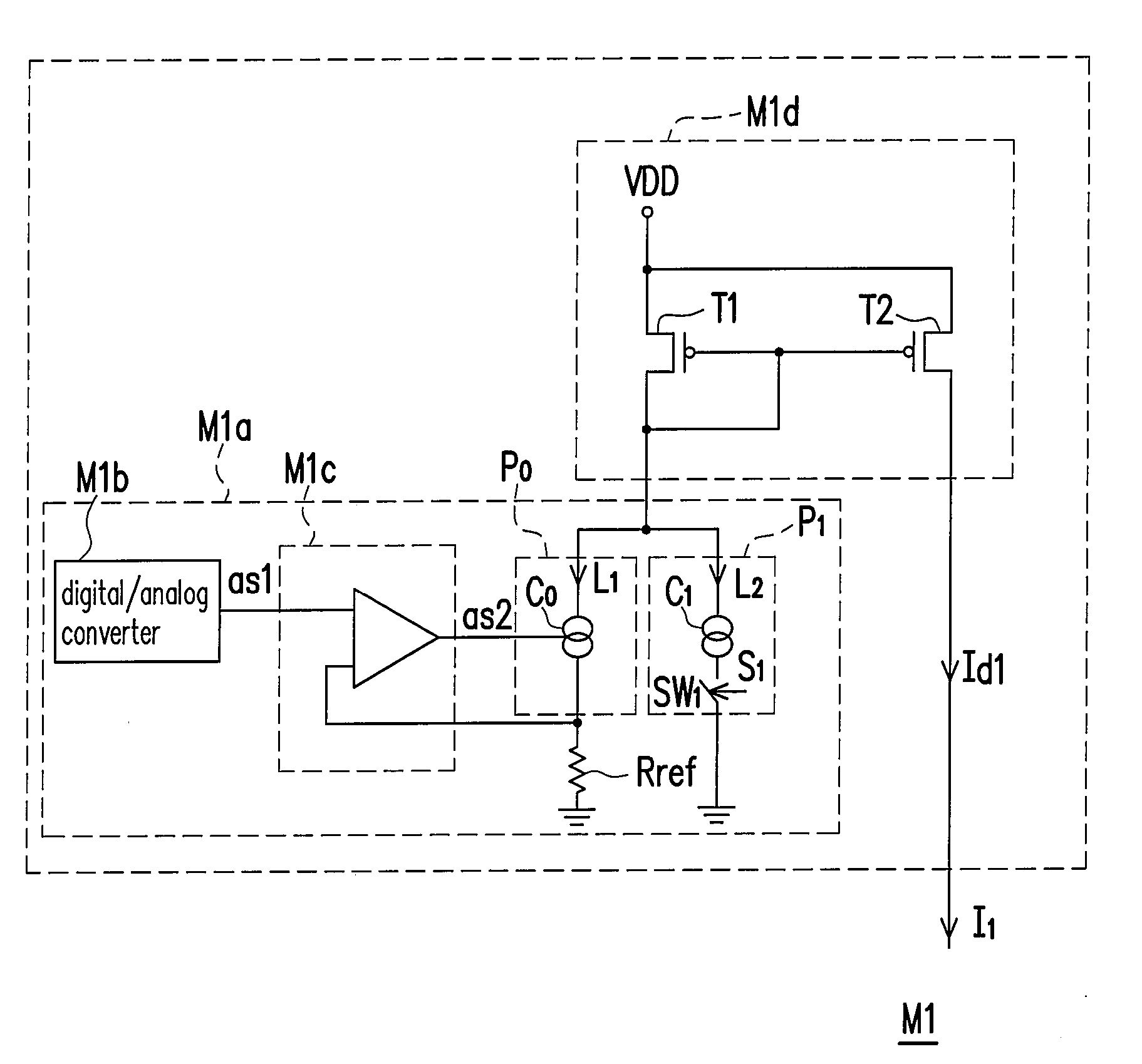
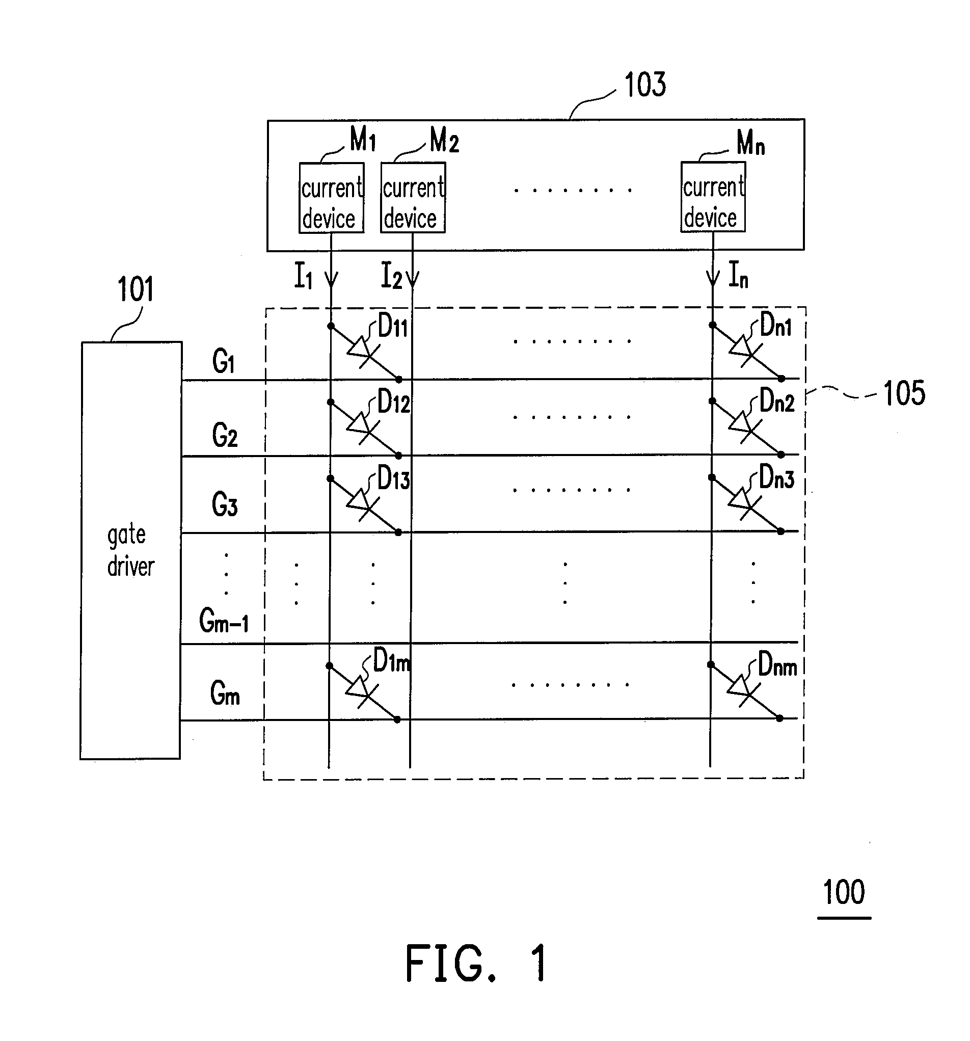
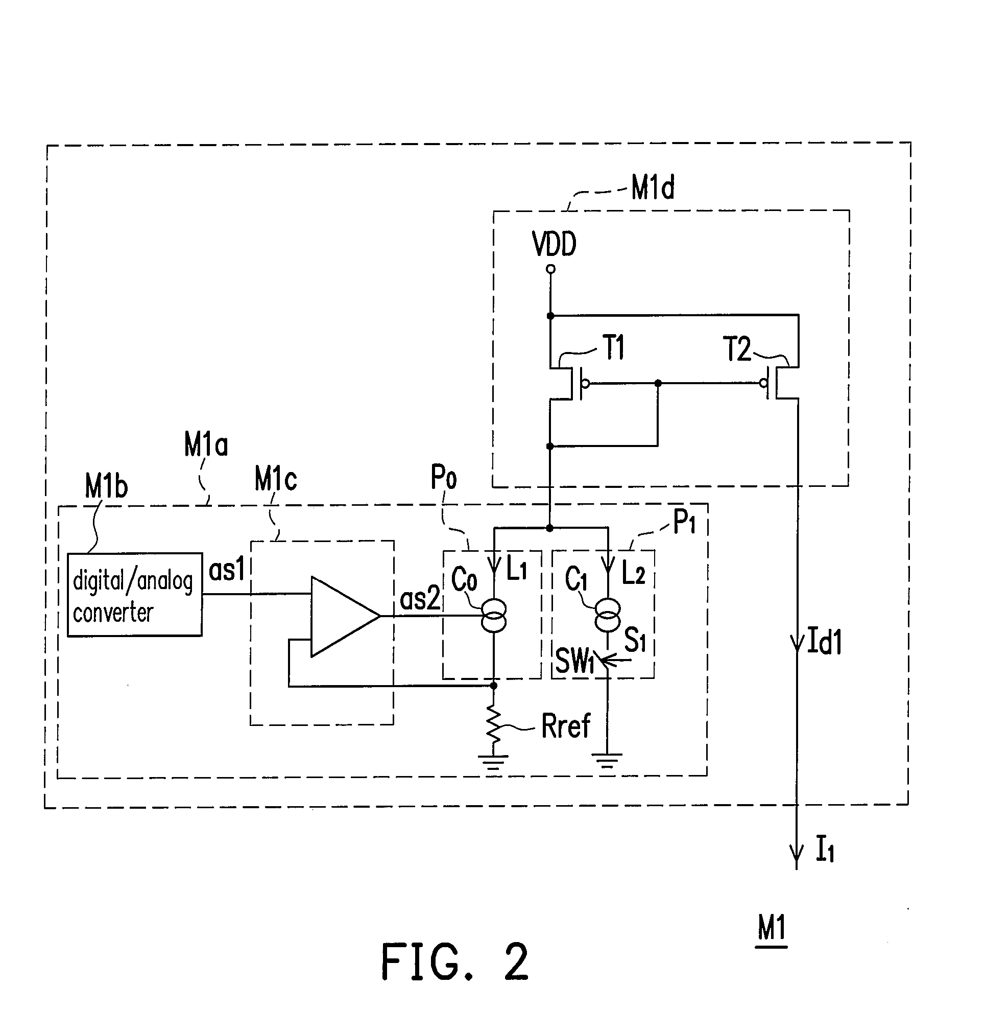
[0030]FIG. 1 is a block diagram of the display according to one preferable embodiment of the present invention. Referring to FIG. 1, the display 100 (for example, a passive OELD) comprises a gate driver 101, a source driver 103 and a display panel 105. The gate driver 101 comprises a plurality of gate wirings G1-Gm for receiving a basic timing and sequentially outputting a scanning voltage Vscan to each of the gate wirings G1-Gm. The source driver 103 comprises a plurality of current-driving units M1-Mn for receiving programming data and outputting data currents Id1-Idn to their corresponding source wirings I1-In.

[0031]The display panel 105 is...


PUM


Abstract

A source driver comprises a plurality of current-driving units, each of which includes a digital to analog converter (DAC), an operational amplifier, a first and second current source, a resistor, and a current mirror unit. The DAC converts programming data to an analog signal. The operational amplifier receives and amplifies the analog signal output from the DAC. The first current source generates a first current according to the amplified analog signal. The resistor is used to supply a feedback path from a reference voltage to the operational amplifier. The second current source outputs a second current according to a control signal generated by the display data. The current mirror unit mirrors a data current according to the sum of the first and second current to drive an organic light-emitting diode (OLED).

Description

CROSS-REFERENCE TO RELATED APPLICATION[0001]This application claims the priority benefit of Taiwan application serial no. 95112368, filed on Apr. 7, 2006. All disclosure of the Taiwan application is incorporated herein by reference.BACKGROUND OF THE INVENTION[0002]1. Field of Invention[0003]The present invention relates to a source driver. More particularly, the present invention relates to a source driver without being affected by a voltage drop of an anode resistor of an organic light-emitting diode (OLED).[0004]2. Description of Related Art[0005]OLEDs, also referred to as organic electro-luminescent displays (OELDs), are self-luminescent elements. With the characteristics of DC low voltage driving capability, high luminance, high efficiency, high contrast value, lightweight, thinness, and high degree freedom of luminescent colors from three primary colors, red (R), green (G), and blue (B) to white (W), OLEDs are considered to be a key point in the development of the next-generati...

Claims


Application Information

Patent Timeline
IPC IPC(8): G09G3/30
CPCG09G3/3216G09G2320/0233G09G3/3283
Inventor HUANG, JIUNN-YAUYEN, CHENG-CHI
Owner HIMAX TECH LTD
Why Eureka
Try Eureka