
Method and apparatus for bandwidth allocation

a bandwidth allocation and bandwidth technology, applied in the field of bandwidth allocation, can solve the problems of discrimination against other users, worse problems, and inp has no direct visibility on the bandwidth utilization of vno subscribers

Pending Publication Date: 2022-07-21
NOKIA SOLUTIONS & NETWORKS OY
View PDF0 Cites 0 Cited by
  • Summary
  • Abstract
  • Description
  • Claims
  • Application Information

AI Technical Summary

Benefits of technology

The patent text describes a method to adjust the amount of network bandwidth allocated to a participant based on their resource availability and previous behavior. This results in a dynamic and closed-loop automation that ensures long-term fairness in resource allocation. In simple terms, the method allows for efficient and effective allocation of network resources.

Problems solved by technology

However, in case of one or more abnormally high demanding or even potentially abusing users, these mechanisms tend to discriminate the other users.
Such situations may happen when residential subscribers would host unusual services creating very high bandwidth request for example in case of P2P storage networks, or when a company would clearly abuse a residential subscription to offer commercial services.
In a slicing context, where a physical access node is virtually divided into multiple virtual access nodes, each of them being managed by a Virtual Network Operator hereafter abbreviated by VNO, serving its own subset of subscribers, the problem is even worse.
However, the InP has no direct visibility on the bandwidth utilization of the VNO subscribers.
Therefore, if the abusing subscriber is not managed properly by the entity of the virtual network serving it, the subscribers of other virtual networks may be impacted as well.
However also these combined scheduler / shaper systems still do not sufficiently cope with the aforementioned problems of potentially abusing users.

Method used


Image

  • Method and apparatus for bandwidth allocation
  • Method and apparatus for bandwidth allocation
  • Method and apparatus for bandwidth allocation

Examples


Embodiment Construction

[0040]Example embodiments of the present application are described herein in detail and shown by way of example in the drawings. It should be understood that, although specific embodiments are discussed herein there is no intent to limit the scope of the invention to such embodiments. To the contrary, it should be understood that the embodiments discussed herein are for illustrative purposes, and that modified and alternative embodiments may be implemented without departing from the scope of the invention as defined in the claims. The sequence of method steps is not limited to the specific embodiments, the method steps may be performed in other possible sequence. Similarly, specific structural and functional details disclosed herein are merely representative for purposes of describing the embodiments. The invention described herein, however, may be embodied in many alternate forms and should not be construed as limited to only the embodiments set forth herein.

[0041]According to the ...


PUM


Abstract

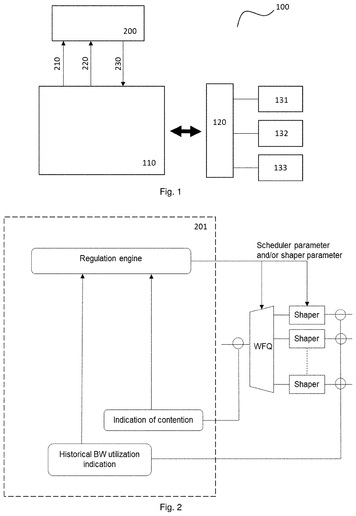
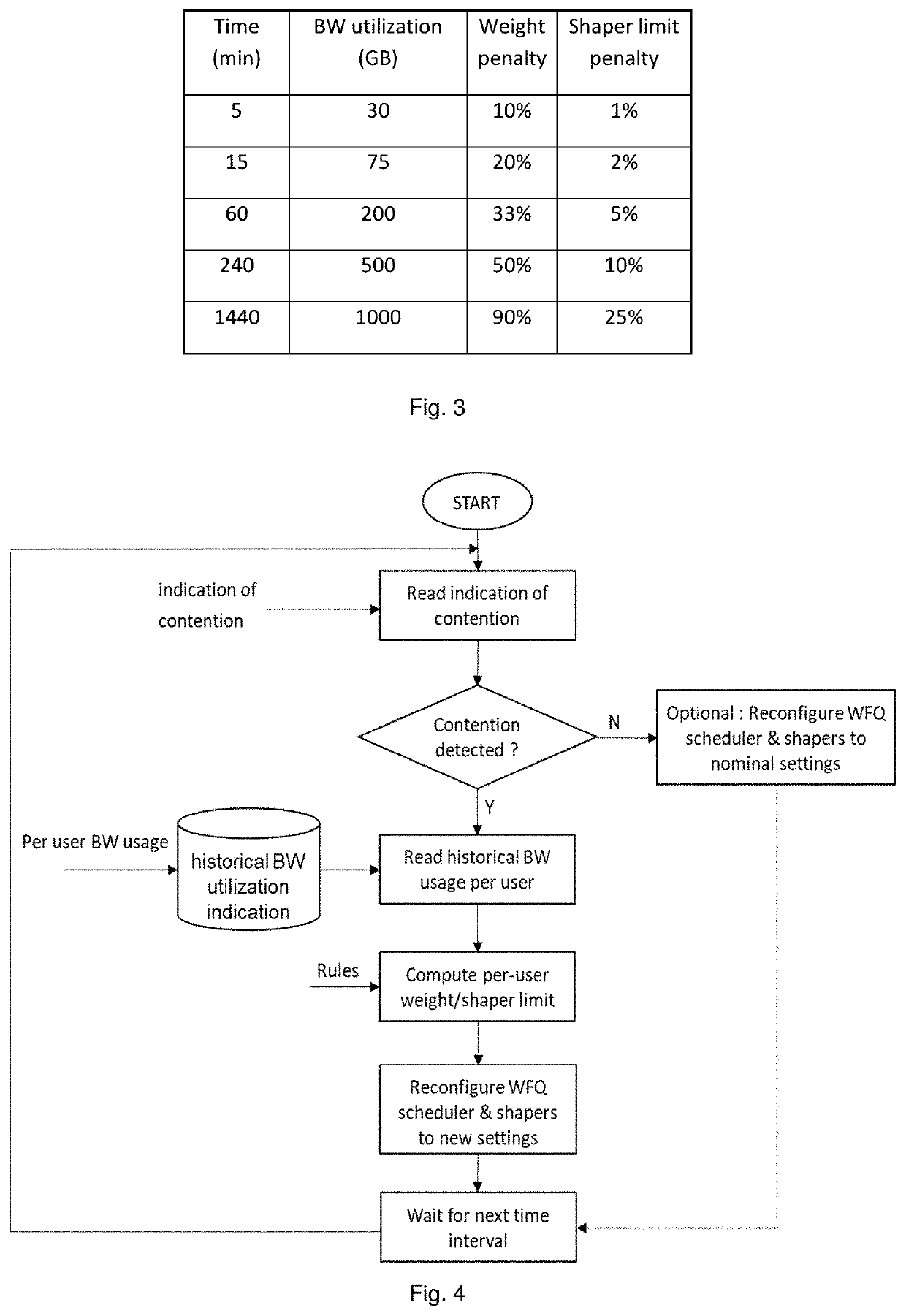
An apparatus including at least one processor, and at least one memory including computer program code. The at least one memory and computer program code configured to, with the at least one processor, cause the apparatus to perform, obtaining an indication of contention of a communications network; obtaining a historical bandwidth utilization indication parameter of respective participants of the communications network; and determining, based on the indication of contention and the historical bandwidth utilization indication, a scheduler parameter and / or a shaper parameter for being provided to an output of the apparatus. The scheduler parameter and / or the shaper parameter is related to allocating bandwidth to a participant of the network.

Description

FIELD OF THE INVENTION[0001]Various example embodiments relate to bandwidth allocation, specifically to determining of scheduler parameter and / or shaper parameter.BACKGROUND[0002]The sharing of bandwidth in a network between multiple clients is typically handled by Weighted Fair Queue (WFQ) scheduler components. In this sharing scheme, a weight is given to each client. Each of them will receive a fraction of the total bandwidth which is proportional to their weight. By design, if any client would not be active or not request his entitled bandwidth fraction, this “free” or spare bandwidth is automatically distributed among the active clients, proportionally to the weights of those active clients. In worst case, the minimum bandwidth that each client will receive is equal to the total bandwidth multiplied by the ratio of its weight over the sum of the weights of all the clients. In best case, if there would be only one active client at a certain time, this client would get the full ba...

Claims


Application Information

Patent Timeline
IPC IPC(8): H04W72/12H04W74/08H04L47/625
CPCH04W72/1257H04L47/6265H04W74/08H04L41/0896H04L47/22H04L47/629H04L47/127H04W72/535
Inventor DROOGHAAG, BENOITDIESTELMANS, JANKORA, SIREESHAFOUZ PEREZ, PEDRO
Owner NOKIA SOLUTIONS & NETWORKS OY
Learn More