Dispensing head and beverage server

Pending Publication Date: 2022-08-04
ASAHI BREWERIES LTD +2
View PDF0 Cites 0 Cited by
  • Summary
  • Abstract
  • Description
  • Claims
  • Application Information

AI Technical Summary

Benefits of technology

[0005]The object of the present invention is to provide a dispensing head and a beverage

Problems solved by technology

Accordingly, the carbon d

Method used


Image

  • Dispensing head and beverage server
  • Dispensing head and beverage server
  • Dispensing head and beverage server

Examples


Example

[0018]Hereinafter, embodiments will be described in detail with reference to the attached drawings. Note, the following embodiments are not intended to limit the scope of the claimed invention, and limitation is not made to an invention that requires a combination of all features described in the embodiments. Two or more of the multiple features described in the embodiments may be combined as appropriate. Furthermore, the same reference numerals are given to the same or similar configurations, and redundant description thereof is omitted.

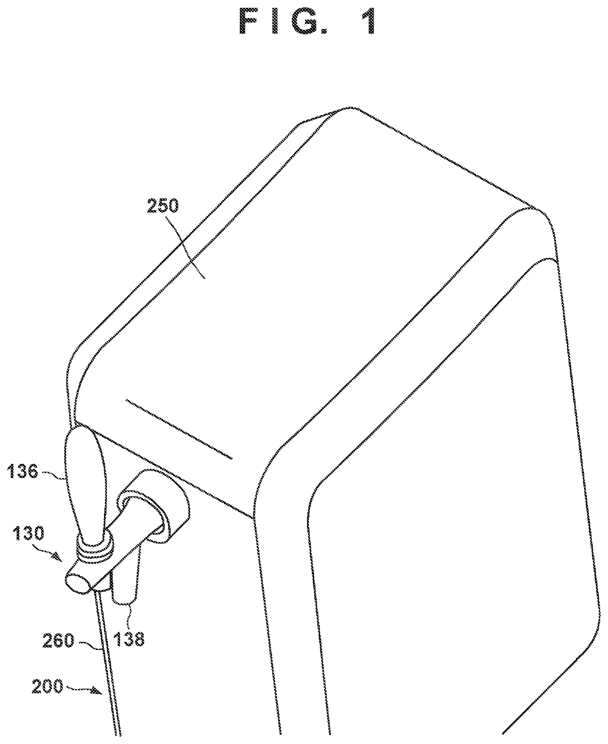
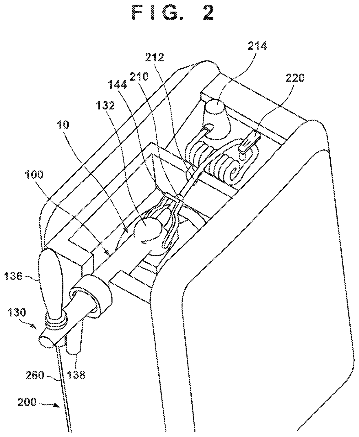
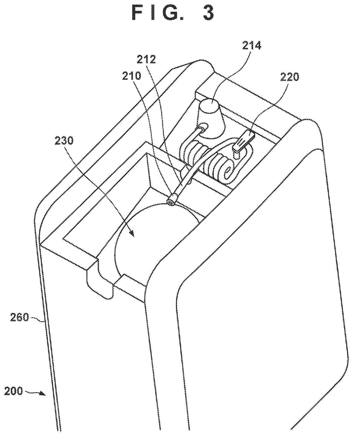
[0019]FIGS. 1, 2, 3, and 4 show an arrangement of a beverage server 200 according to an embodiment of the present invention. The beverage server 200 is arranged to dispense a beverage (for example, beer) in a beverage container 10 into a container such as a mug or glass from a dispensing port 138 using the pressure of the gas such as carbon dioxide gas. The beverage server 200 can include a main body 260 and a dispensing head 100. The main body 260 ...


PUM


Abstract

A dispensing head includes a fastening portion fastened to a mouth of a beverage container, a connecting portion to which a gas coupling connected to a gas cylinder via a gas tube is connected, a gas channel configured to cause the connecting portion and the beverage container to communicate with each other, a dispensing portion configured to dispense a beverage injected from the beverage container by a pressure of a gas supplied to the beverage container via the gas channel, and an operation inhibition mechanism configured to inhibit an operation for connecting the gas coupling to the connecting portion in a state in which the fastening portion is not fastened to the mouth.

Description

CROSS-REFERENCE TO RELATED APPLICATION(S)[0001]This application is a continuation of International Patent Application No. PCT / JP2020 / 040919 filed on Oct. 30, 2020, which claims priority to and the benefit of Japanese Patent Application No. 2019-200204 filed on Nov. 1, 2019, the entire disclosures of which are incorporated herein by reference.FIELD OF THE INVENTION[0002]The present invention relates to a dispensing head and a beverage server.DESCRIPTION OF THE RELATED ART[0003]Japanese Patent Laid-Open No. 2002-68381 describes a beer server for supplying beer by supplying carbon dioxide gas to a beer container. The beer server includes a lower base portion including a cooler, a mount body mounted on the mouth of the beer container, and a tap for dispensing beer supplied from the mount body. Carbon dioxide gas is supplied from a carbon dioxide gas cartridge to the mount portion via a carbon dioxide gas tube.[0004]In the beer server described in Japanese Patent Laid-Open No. 2002-68381...

Claims


Application Information

Patent Timeline
IPC IPC(8): B67D1/08B67D1/04
CPCB67D1/08B67D2001/0822B67D1/04B67D1/0406B67D1/0801B67D1/0839B67D1/0848B67D1/0845B67D1/0412
Inventor KURABE, YASUHIROKUDO, YOSHIHIROHOSONO, HIROTSUGUKOBAYASHI, TAKAHIDE
Owner ASAHI BREWERIES LTD
Why Eureka
Try Eureka