Combined cycle power station with gas turbine cooling air cooler

a technology of gas turbine and cooling air cooler, which is applied in the direction of steam generation using hot heat carriers, machines/engines, mechanical equipment, etc., can solve the problems of high-quality heat of cooling air, unavoidable cooling of combustion chambers, and rotors and blading, and achieve the effect of 20 mw of high-quality hea

Inactive Publication Date: 2000-02-01
GENERAL ELECTRIC TECH GMBH
View PDF7 Cites 36 Cited by
  • Summary
  • Abstract
  • Description
  • Claims
  • Application Information

AI Technical Summary

Benefits of technology

When such an apparatus is used in a combined process, the advantage may be seen inter alia in that high-quality heat is fully retained within the process. Combining different steam parameters--which are the result of the waste heat boiler, on the one hand, and of the gas turbine cooling air cooler, on the other--in the se

Problems solved by technology

Gas turbines of the modern generation and the higher power class operate with very high turbine inlet temperatures, which makes cooling of the combustion chambers, the rotors and the blading unavoidable.
Cooling by means of water injection ("gas quenching") is known for this purpose;

Method used


Image

  • Combined cycle power station with gas turbine cooling air cooler

Examples


Embodiment Construction

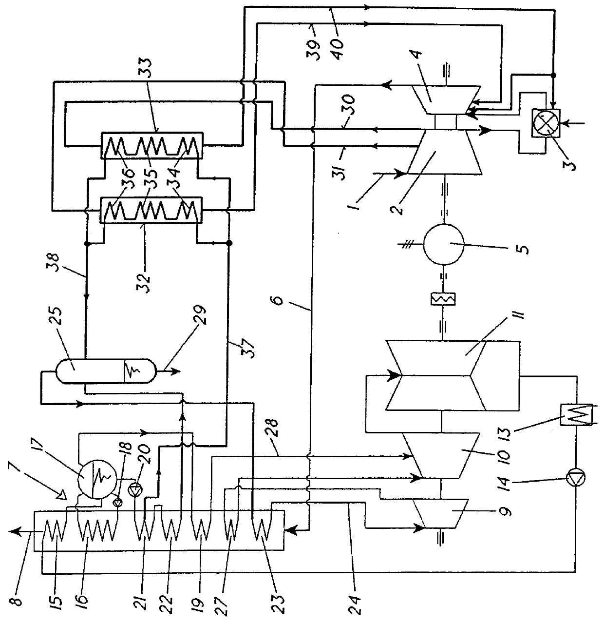
Referring now to the individual figure in the drawing, where only the elements essential to the understanding of the invention are shown and where the flow direction of the working media is indicated by arrows, fresh air induced in the gas turbine system via a line 1 is compressed in a compressor 2 to the working pressure. The compressed air is greatly heated in a combustion chamber 3 which is fired, for example, by natural gas and the combustion gas arising in this manner is expanded in a gas turbine 4 with the output of power. The energy thus gained is supplied to a generator 5 and to the compressor 2. The gas turbine exhaust gas, which is still hot, is fed via a line 6 from the outlet of the gas turbine to a waste heat steam generation installation 7 and is led from there, after giving up its heat, via a line 8 and a chimney (not shown) to the open air.

In the water / steam cycle, a multi-cylinder steam turbine 9, 10 and 11 is arranged on the same shaft as the gas turbine. The worki...


PUM


Abstract

In a combined power station installation with a gas turbine (4) and a steam turbine (9-11), the exhaust gases from the gas turbine give up their residual heat to the steam turbine via the working medium flowing in a waste heat boiler (7). The waste heat boiler consists essentially of an economizer (21), an evaporator (22) and a superheater (23). A cooling air cooler (32, 33) designed as a once-through steam generator is connected on the water side to the economizer (21) of the waste heat boiler (7). The waste heat boiler is a once-through steam generator in which a separation bottle (25) is arranged on the steam side between the evaporator (22) and the superheater (23). The cooling air cooler (32, 33) is connected on the steam side to the separation bottle (25).

Description

BACKGROUND OF THE INVENTION1. Field of the InventionThe invention relates to a combined power station installation with a gas turbine and a steam turbine, in which the exhaust gases from the gas turbine give up their residual heat to the steam turbine via the working medium flowing in a waste heat boiler, whereby the waste heat boiler consists essentially of an economizer, an evaporator and a superheater and whereby at least one cooling air cooler is provided which is designed as a forced circulation steam generator and is connected on the water side to the economizer of the waste heat boiler.2. Discussion of BackgroundGas turbines of the modern generation and the higher power class operate with very high turbine inlet temperatures, which makes cooling of the combustion chambers, the rotors and the blading unavoidable. For this purpose, highly compressed air is generally extracted at the compressor outlet and, if appropriate, from a lower pressure stage. Because a very high proporti...

Claims


Application Information

Patent Timeline
IPC IPC(8): F01K23/10F02C7/18F02C7/16F01K17/04F02C6/18F22B1/18
CPCF01K23/106F02C7/185Y02E20/16
Inventor LIEBIG, ERHARD
Owner GENERAL ELECTRIC TECH GMBH
Why Eureka
Try Eureka