Cable cutter with insert blades

a cutting blade and cable cutter technology, applied in the field of hand cutting tools, can solve the problems of increasing the wear of the cutting surface, affecting the workpiece, and affecting the use of the tool

Inactive Publication Date: 2000-07-18
MIDWEST TOOL & CUTLERY
View PDF10 Cites 18 Cited by
  • Summary
  • Abstract
  • Description
  • Claims
  • Application Information

AI Technical Summary

Problems solved by technology

These simple tools typically are made of forged high carbon steel, which experiences significant wear if harder materials, such as aluminum or copper, are cut.
However, the leverage provided by the linkage applies a much greater force to the workpiece than the simple hinged tools.
With the significantly higher force of compound linkages and the corresponding ability to cut harder materials comes an increase in wear to the cutting surfaces.
The use of materials for the cutting surfaces that do not wear as severely increases the cost of the tool significantly, because the entire tool, or at least a significant portion of it, must be made of the harder, more expensive material.
The cost of the insert blades is lower than if the entire tool, or even a significant portion of it, were made of the more expensive, harder material.

Method used


Image

  • Cable cutter with insert blades
  • Cable cutter with insert blades
  • Cable cutter with insert blades

Examples


Embodiment Construction

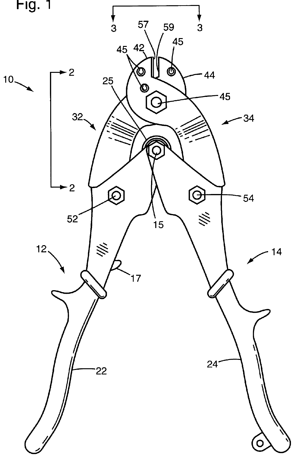
The preferred cable cutter 10 has a pair of handles 12 and 14 that are pivotably mounted together by a fastener, such as the handle pivot screw 15, extending through the engaged ends of the handles 12 and 14. High-friction hand grips 22 and 24 cover the lower portion of the handles 12 and 14 to provide user comfort and a secure grip on the handles 12 and 14. A conventional latch 17, shown in FIG. 5, extends from the handle 12 to latch onto the screw 54 in the handle 14, as shown in FIG. 6.

The handles 12 and 14 are hand-grippable, meaning that an average person can grasp the handles 12 and 14 between the thumb and opposed fingers, or alternatively the heel of the hand and opposed fingers, and squeeze the handles together. The average person can generate a sufficient force to pivot one handle relative to the other about the handle pivot screw 15.

The levers 32 and 34 are pivotably mounted together by a fastener, such as the lever pivot screw 35, extending through the overlapped midsect...


PUM

PropertyMeasurementUnit
gap widthaaaaaaaaaa
thicknessesaaaaaaaaaa
forceaaaaaaaaaa

Abstract

A cable cutting tool with high hardness insert blades inserted between pivotably mounted levers. The levers are pivotably mounted to hand-grippable handles. The levers have jaws with a gap formed between inner facing surfaces thereof. The gap provides space for insertion of the insert blades.

Description

1. Field of the InventionThe invention relates to hand tools, and more particularly to hand cutting tools actuated by squeezing hand-grippable handles together to bring cutting surfaces in shearing action past one another.2. Description of the Related ArtHand cutting tools are used to cut wire, cable and sheet material. Cutting tools can simply consist of a pair of elongated handles that are pivotably mounted together at an intersection point near one end. A sharpened cutting surface of one handle is forced against a blunt anvil on the other handle, thereby cutting a workpiece that is placed between the two surfaces. Alternative cutting actions can be used, including shearing with scissoring action. These simple tools typically are made of forged high carbon steel, which experiences significant wear if harder materials, such as aluminum or copper, are cut.More recently, compound linkages have been used on cutting tools to permit a greater force to be applied to the workpiece upon sq...

Claims


Application Information

Patent Timeline
Patent Type & Authority Patents(United States)
IPC IPC(8): B26B17/00B26B17/02
CPCB23D29/023B23D35/002
Inventor SCHMICK, DANIEL G.
Owner MIDWEST TOOL & CUTLERY
Why Eureka
Try Eureka