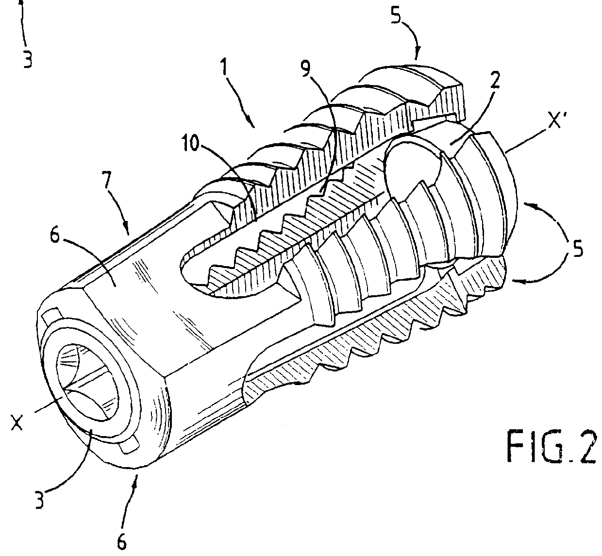
To provide better anchoring in the bone and to avoid any subsequent migration of the cage, the outside surfaces of said branches are preferably either knurled, grooved, or threaded using a thread profile having projecting ridges, etc.
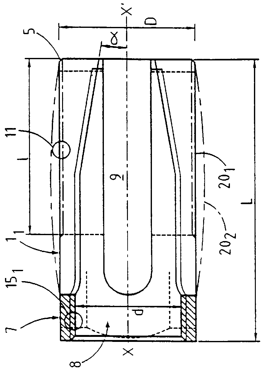
Also, to reduce any risk of rotation after implantation, and thus reduce any risk of displacement of the cage, while simultaneously increasing contact area with the faces of the vertebrae, at least the seat of the
implant and preferably also the sides of the branches have at least two optionally parallel flats, each disposed symmetrically about the axis of the implants between two successive branches. These flats, optionally assisted by the generally
ovoid shape of the cage, make better retention possible after expansion by reducing any risk of the implant rotating. In addition, said
ovoid shape can make it possible, better than if the outer generator line of the basic cylindrical shape of the cage at rest were a straight line, to return after expansion to an outside profile that is conical and without curvature, thereby providing better-distributed thrust against the body of the vertebrae, thus helping the bone graft to take better.
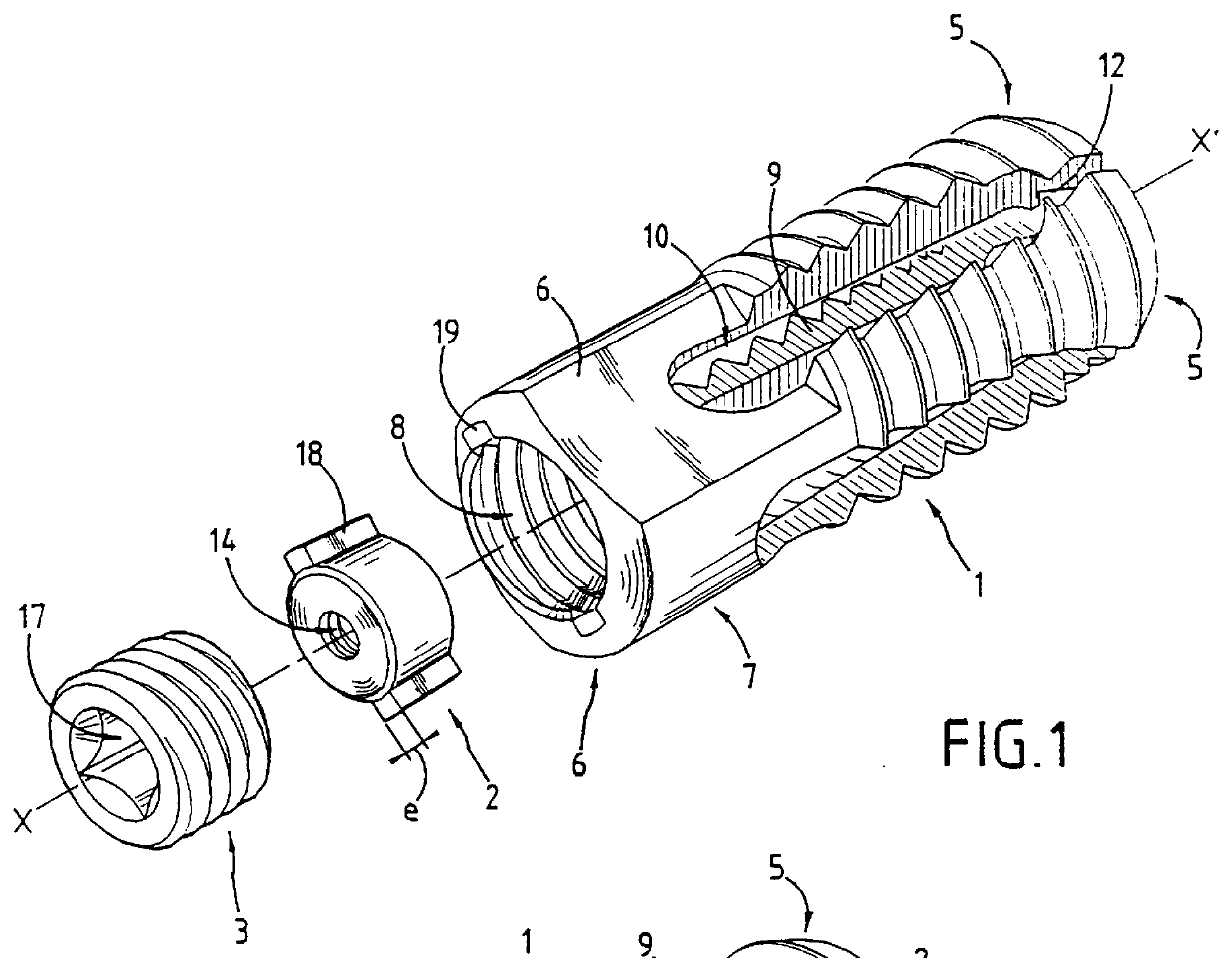
To stiffen the cage at its posterior end, particularly if there is a large orifice in the seat, thereby making it easier to fill the cage with bone matter after the cage has been put into place and expanded, the orifice of said seat is suitable for receiving a plug for closing the inside volume of the cage. By way of example, the plug can be screwed into said orifice, in which case the orifice is also threaded. Under such circumstances, the plug prevents bone matter from escaping and depending on the material out of which it is made, it can also stiffen the cage.
The presence of at least four branches, and possibly four to eight branches, makes it possible to obtain bilateral expansion, and thereby better jamming against the two facing faces of the vertebrae, and the absence of a link part or rod between the spacer maintaining said expansion and the orifice or
plug in the end seat guarantees a larger inside volume for receiving a large quantity of bone matter, thereby improving consolidation and joining by fusion, in particular between the vertebrae that are to be held together. Said filling operation is made that much easier by having a large orifice at the posterior end of the cage through said seat.
In addition, said orifice makes it possible to scrape the faces of the vertebrae through the slots situated between the branches in the bottom and top faces of the cage.
The present invention thus provides numerous advantages over existing implants or cages, of the kind already mentioned, and other advantages can also be provided but those given above suffice to demonstrate the novelty and the usefulness of the invention.

