Low inductance high energy inductive ignition system

a high-energy, inductive ignition and low-inductance technology, applied in mechanical equipment, machines/engines, lighting and heating apparatus, etc., can solve the problems of reducing the energy that can be stored in the core and delivered to the spark gap, sspe is not useful for spark duration, and is impractical for conventional ignition

Inactive Publication Date: 2000-11-07
WARD MICHAEL A V
View PDF5 Cites 77 Cited by
  • Summary
  • Abstract
  • Description
  • Claims
  • Application Information

AI Technical Summary

Problems solved by technology

While energy delivery efficiency of plug-mounted coils increases due to elimination of the distributor and spark plug wires, the constraints on the coil size reduce the energy that can be stored in the core and delivered to the spark gap.
On the other hand, the SSPE is not useful for spark duration, giving values approximately 80% and 33% for the glow and arc discharge respectively.
Such high SSPE for compact ignition coils of preferred volume of 30 to 60 cc (cubic centimeters), approximately 30 cc for 150 mj pencil coils, approximately 40 cc for 200 mj block coils, and approximately 60 cc for 300 mj cylindrical coils, are achievable with the hybrid inductive ignition (HBI disclosed herein and are impractical for conventional ignition.

Method used


Image

  • Low inductance high energy inductive ignition system
  • Low inductance high energy inductive ignition system
  • Low inductance high energy inductive ignition system

Examples


Embodiment Construction

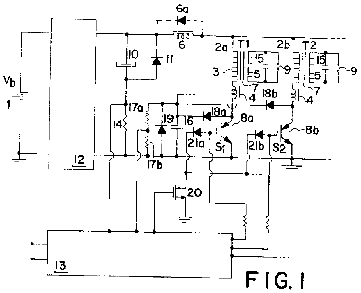
FIG. 1 is a partial block diagram, partial circuit diagram of an embodiment of the (HBI) ignition depicting the power converter (12) and trigger input ignition controller (13) as blocks to be shown in preferred embodiment form in FIG. 10, and depicting the preferred form of distributorless ignition of one coil and one power switch per spark plug (of a multi-cylinder engine), depicting two coils of any number of coils, and assuming for simplicity, where required, a conventional 4-cylinder engine with four coils and four power switches.

The ignition assumes operation from a 12 volt car battery 1 (voltage Vb), with two ignition coils 2a and 2b of several possible shown stacked in parallel (also designated as T1, T2, or more generally Ti, where the "i" designates the ith transformer coil). Each coil has primary winding 3 of inductance Lp, turns Np, and coil primary leakage inductance 4 (inductance Lpe) shown as separate inductors, secondary windings 5 of inductance Ls, turns Ns, terminat...


PUM

PropertyMeasurementUnit
operating voltageaaaaaaaaaa
voltageaaaaaaaaaa
voltageaaaaaaaaaa

Abstract

PCT No. PCT/US96/19898 Sec. 371 Date Apr. 21, 1999 Sec. 102(e) Date Apr. 21, 1999 PCT Filed Dec. 12, 1996 PCT Pub. No. WO97/21920 PCT Pub. Date Jun. 19, 1997A high power, high energy inductive ignition system with a parallel array of multiple ignition coils Ti (2a, 2b) and associated 600 volt unclamped IGBT power switches Si (8a, 8b), for use with an automotive 12 volt storage battery (1), the system having an internal voltage source (12) to generate a voltage Vc approximately three times the peal primary coil current with coils Ti of low primary inductance of about 0,5 millihenry and of open E-type core structure for spark energy in the range of 120 to 250 mj, the system using a lossless snubber and variable control inductor (6) to provide very high circuit and component efficiency and high coil energy density, in mj/gm, three times that of conventional inductive ignition systems, and high output voltage of 40 kilovolts with fast rise time of 10 microseconds.

Description

BACKGROUND OF THE INVENTION AND PRIOR ARTThere is a move in the automotive industry to distributorless ignition systems of one coil per spark plug, and particularly towards plug-mounted coils. Motivations for this are more compact ignition, elimination of electromagnetic interference, and higher ignition efficiency (no distributor or spark plug wires), as well as other reasons.There is also a desire to maintain and even raise, the spark plug energy that is delivered to the combustible mixture for ignition. While energy delivery efficiency of plug-mounted coils increases due to elimination of the distributor and spark plug wires, the constraints on the coil size reduce the energy that can be stored in the core and delivered to the spark gap. The coil winding resistance increases as the coil diameter is reduced in inverse relationship to the fourth power of the diameter, to make the coil ever less efficient as it is made smaller. The high coil primary inductance Lp of 2 to 8 milliHenr...

Claims


Application Information

Patent Timeline
Patent Type & Authority Patents(United States)
IPC IPC(8): F02P9/00F02P3/02F02P3/04F02P3/00H01F38/12H01F38/00F02P7/03
CPCF02P3/005H01F38/12F02P9/002F02P3/0442F02P3/0876
Inventor WARD, MICHAEL A. V.
Owner WARD MICHAEL A V
Why Eureka
Try Eureka