Flexible packaging for polymer electrolytic cell and method of forming same

a polymer electrolytic cell and flexible technology, applied in the field of packaging and enclosures, can solve the problems of difficult assembly of batteries in unusually shaped metal or plastic enclosures, high internal pressure, and shape restrictions, and achieve the effect of reducing packaging space and maximizing battery energy density

Inactive Publication Date: 2000-11-14
NGK SPARK PLUG CO LTD
View PDF16 Cites 78 Cited by
  • Summary
  • Abstract
  • Description
  • Claims
  • Application Information

AI Technical Summary

Benefits of technology

Another object of the present invention is to provide a method of packaging batteries as described above which maximizes the energy density of the battery.
Another object of the present invention is to provide a method of packaging batteries as described above that reduces the packaging space necessary for hermetically sealing the electrolytic cell.

Problems solved by technology

In this respect, in some types of batteries, internal gas buildup may occur resulting in relatively high internal pressures.
While metal and molded plastic containers are sturdy and volume efficient, they are somewhat shape restrictive.
However, when a specific application or product requires a battery having an unusual shape, such as an extremely thin battery or a non-planar or non-prismatic battery, the assembly of a battery in an unusually shaped metal or plastic enclosure becomes more difficult.
With smaller batteries, the metal cans or molded plastic cases previously described decrease the measure of the "energy density" of such batteries.
However, if the final package is not carefully configured, any potential weight and shape advantage of the flexible packaging may be lost, or the overall volume may even increase due to the packaging configuration.
The advantages of a flexible laminate packaging may also be lost when packaging a non-aqueous battery, such as a high-energy lithium ion battery.
As can be seen in FIG. 1, the sealed regions of the laminate that extend about the three sides of the cell occupy a significant amount of space.
This built-up region of overlapping layers of the laminate reduces the volume efficiency, i.e., the "energy density" of the battery.
Another problem associated with flexible packaging is forming a hermetic seal around the battery leads that extend through the packaging.
Because the heat and pressure that can be applied to the laminate when forming the battery package (i.e., sealing the edges) must be limited so as not to tear the laminate during the sealing process, creating a complete and permanent seal about the feedthroughs is a major problem in flexible laminate packaging. FIG. 10 pictorially illustrates how voids may form along the edges of a feedthrough as a result of the limited heat and pressure that can be applied to the flexible laminate during a conventional sealing process.
Such voids may allow air or moisture to penetrate the package or may allow electrolyte to escape from the package, both of which basically destroy the effectiveness of the battery.
Excessive heat and pressure, on the other hand, can create the problem shown in FIG. 11, wherein the metal foil layer of the laminate is pressed near or into contact with the feedthrough, as the softened adhesive material is forced laterally by the pressure of a forming platen.

Method used


Image

  • Flexible packaging for polymer electrolytic cell and method of forming same
  • Flexible packaging for polymer electrolytic cell and method of forming same
  • Flexible packaging for polymer electrolytic cell and method of forming same

Examples


Embodiment Construction

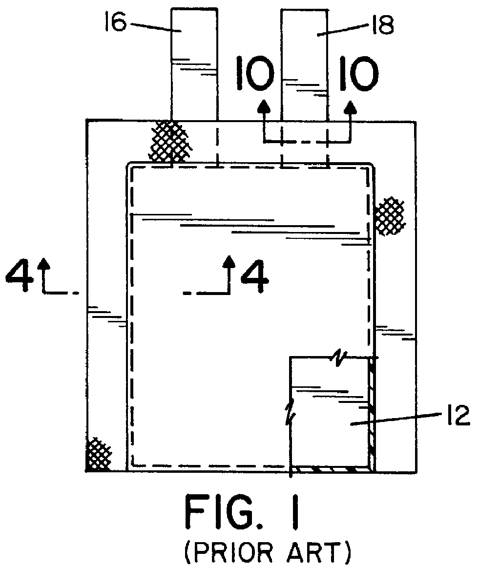
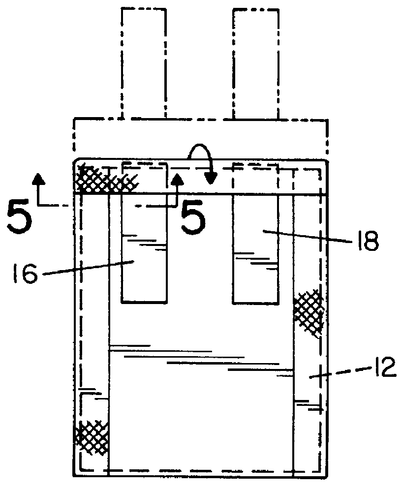
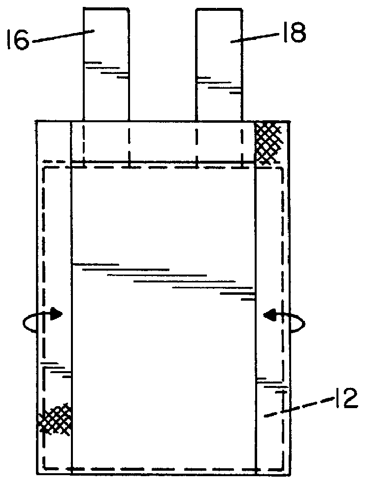
Referring now to the drawings wherein the showings are for the purpose of illustrating preferred embodiments of the invention only, and not for the purpose of limiting same, FIG. 6 illustrates a battery 10 packaged in accordance with the present invention. In the embodiment shown, a planar, solid polymer electrolytic battery 10 is illustrated. It will, of course, be appreciated from a further reading of the specification that the present invention may be applied to other types and shapes of battery cells, and is not limited to planar solid polymer electrolytic cells. Battery 10 is generally comprised of a polymer electrolytic cell 12 contained within a package 14. Cell 12 (best illustrated in FIG. 12) is generally flat and rectangular in shape and includes two spaced-apart leads 16 and 18 extending from one side thereof. Cell 12 may be of a type disclosed in U.S. Pat. No. 5,183,715 to North, the disclosure of which is expressly incorporated herein by reference. Leads 16 and 18 that ...


PUM

PropertyMeasurementUnit
thicknessaaaaaaaaaa
thicknessaaaaaaaaaa
thickaaaaaaaaaa

Abstract

A method of packaging a rectangular electrolytic battery, comprising the steps of forming a sleeve from a flat, rectangular sheet of a laminate material by overlapping and joining opposite edges of the sheet; inserting a rectangular battery into one end of the sleeve, the battery having two electronic contacting leads extending from one side thereof and the battery being positioned within the sleeve wherein a portion of the leads is within the sleeve and a portion of the leads is outside said sleeve; joining the ends of the sleeve to form a seal along each end thereof, hermetically sealing the interior of the sleeve, one end of the sleeve forming a seal about the leads and the other end of the sleeve sealed adjacent the battery.

Description

FIELD OF THE INVENTIONThe present invention relates generally to electrochemical devices using liquid or polymer electrolytes or requiring hermetic packaging, and more particularly, to packaging and enclosures for encasing and hermetically sealing an electrolytic cell or battery.BACKGROUND OF THE INVENTIONImprovements in microelectronics have increased the demand for electrolytic cells and batteries that can be directly incorporated into electronic devices so as to produce a portable, finished package. As the improvements in microelectronics reduce the size of the electronic device, the space allotted to a power supply within such device has likewise decreased. It is therefore important to maximize the power-per-unit space that a battery cell can provide. One way to improve power-per-unit space is to reduce the size of the packaging or enclosure containing the electrolytic cell.Traditionally, batteries, particularly small batteries, are packaged in metal cans (e.g., cylindrical batt...

Claims


Application Information

Patent Timeline
Patent Type & Authority Patents(United States)
IPC IPC(8): H01M2/02H01M2/30H01M50/119H01M50/121H01M50/129H01M50/133H01M50/178H01M50/55H01M50/553H01M50/562
CPCH01M2/0275Y10T29/4911H01M2/30H01M2/0287Y02E60/10H01M50/124H01M50/562H01M50/133H01M50/121H01M50/129H01M50/178H01M50/55H01M50/553H01M50/119
Inventor DAROUX, MARK L.GLOVER, DAVID A.RICZINGER, RICHARD F.MACKELL, ALLEN D.
Owner NGK SPARK PLUG CO LTD
Why Eureka
Try Eureka