Tube assembly for heating and air conditioning system

a technology of heating and air conditioning system and tube assembly, which is applied in the direction of indirect heat exchangers, light and heating apparatus, transportation and packaging, etc., can solve the problems of no heat exchange between supply and return lines, packaging problems,

Inactive Publication Date: 2000-11-14
TI GRP AUTOMOTIVE SYST LLC
View PDF13 Cites 44 Cited by
  • Summary
  • Abstract
  • Description
  • Claims
  • Application Information

AI Technical Summary

Problems solved by technology

One disadvantage of the above is that separate lines are needed for supply and return of fluid which creates a packaging problem.
Another disadvantage of the above is that there is no heat exchange between the supply and return lines.

Method used


Image

  • Tube assembly for heating and air conditioning system
  • Tube assembly for heating and air conditioning system
  • Tube assembly for heating and air conditioning system

Examples


Embodiment Construction

)

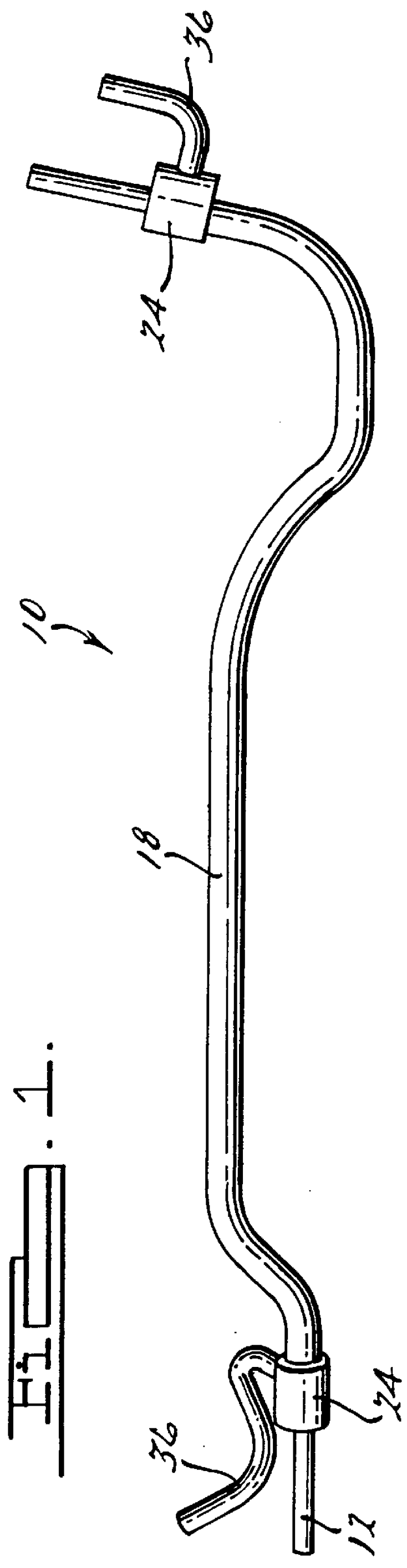
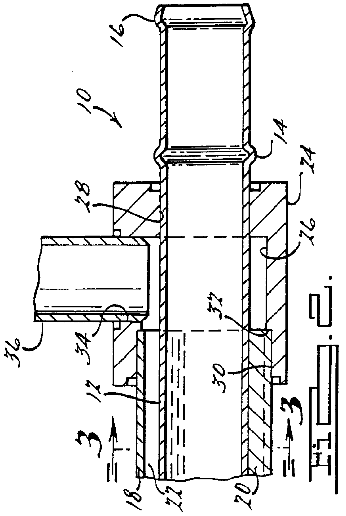
Referring to FIGS. 1 through 3, a tube assembly 10, according to the present invention, is shown for an auxiliary heating and air conditioning system (not shown) of a motor vehicle (not shown). The tube assembly 10 includes an inner tube 12 extending longitudinally to supply fluid such as water from a front or main heating and air conditioning system (not shown) to the rear or auxiliary heating and air conditioning system. The inner tube 12 is hollow and has a generally circular cross-sectional shape. The inner tube 12 may have bead 14 and a radially expanded end 16 for connection to a hose (not shown). The inner tube 12 is made of a rigid material such as a metal material.

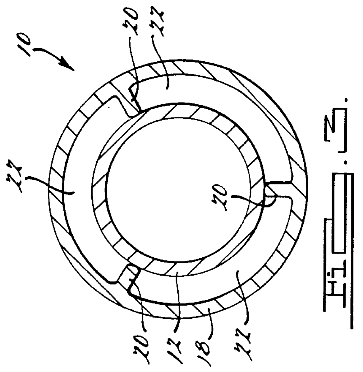
The tube assembly 10 also includes an outer tube 18 extending longitudinally and disposed over the inner tube 12. The outer tube 18 is hollow and has a generally circular cross-sectional shape and also has the same cross sectional area as the inner tube 12. The outer tube 18 includes a plurality of ribs 20 extend...


PUM


Abstract

A tube assembly for an auxiliary heating and air conditioning system includes an inner tube extending longitudinally, an outer tube extending longitudinally and disposed over the inner tube, the outer tube including a plurality of ribs for locating the inner tube approximately concentric to the outer tube, at least one connector tube, and at least one connector interconnecting the at least one connector tube and the outer tube to allow fluid flow between the inner tube and the outer tube.

Description

1. Field of the InventionThe present invention relates generally, to heating and air conditioning systems and, more particularly, to a tube assembly for an auxiliary heating and air conditioning system of a motor vehicle.2. Description of the Related ArtMotor vehicles typically include a heating and air conditioning system for heating and cooling of an occupant compartment of the motor vehicle. Often, these heating and air conditioning systems include an auxiliary heating and air conditioning system. Typically, a fluid supply line extends from a main heating and air conditioning system to the auxiliary heating and air conditioning system and a fluid return line extends from the auxiliary heating and air conditioning system to the main heating and air conditioning system.One disadvantage of the above is that separate lines are needed for supply and return of fluid which creates a packaging problem. Another disadvantage of the above is that there is no heat exchange between the supply...

Claims


Application Information

Patent Timeline
Patent Type & Authority Patents(United States)
IPC IPC(8): B60H1/00F28D7/10
CPCB60H1/00342F28D7/106B60H1/00571B60H1/00557F28D7/10
Inventor HARTNAGEL, PHILIP S.POTHEN, KURIANMOURAD, MATTHEWHUTCHINGS, JAMES
Owner TI GRP AUTOMOTIVE SYST LLC
Why Eureka
Try Eureka