Mud box for joint compound application

a mud box and joint compound technology, applied in the field of mud boxes, can solve the problems of increasing the ungainly use and filling of the entire mud box, increasing the work of the operator, and increasing the difficulty of overcoming the tension of the spring, so as to achieve the effect of convenient us

Inactive Publication Date: 2000-11-14
EQUITY EARNINGS
View PDF11 Cites 55 Cited by
  • Summary
  • Abstract
  • Description
  • Claims
  • Application Information

AI Technical Summary

Problems solved by technology

The problem with prior art mud boxes is that the springs attached to the cover are affixed so as to bias the cover toward the open position to aid in opening and filling the mud box and to ensure that joint compound is not extruded or ejected from the box continuously, i.e. no joint compound should be extruded when the operator releases pressure on the handle or cover of the mud box.
Since mud boxes are generally used by professionals who spend complete days applying joint compound to drywall and the like, the additional spring tension that must be overcome can become a great deal of extra work for the operator.
However, without the springs the cover is simply pivotally attached along one edge and the entire mud box is more ungainly to use and to fill.

Method used


Image

  • Mud box for joint compound application
  • Mud box for joint compound application
  • Mud box for joint compound application

Examples


Embodiment Construction

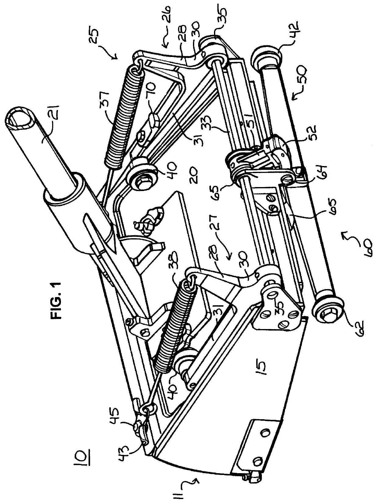
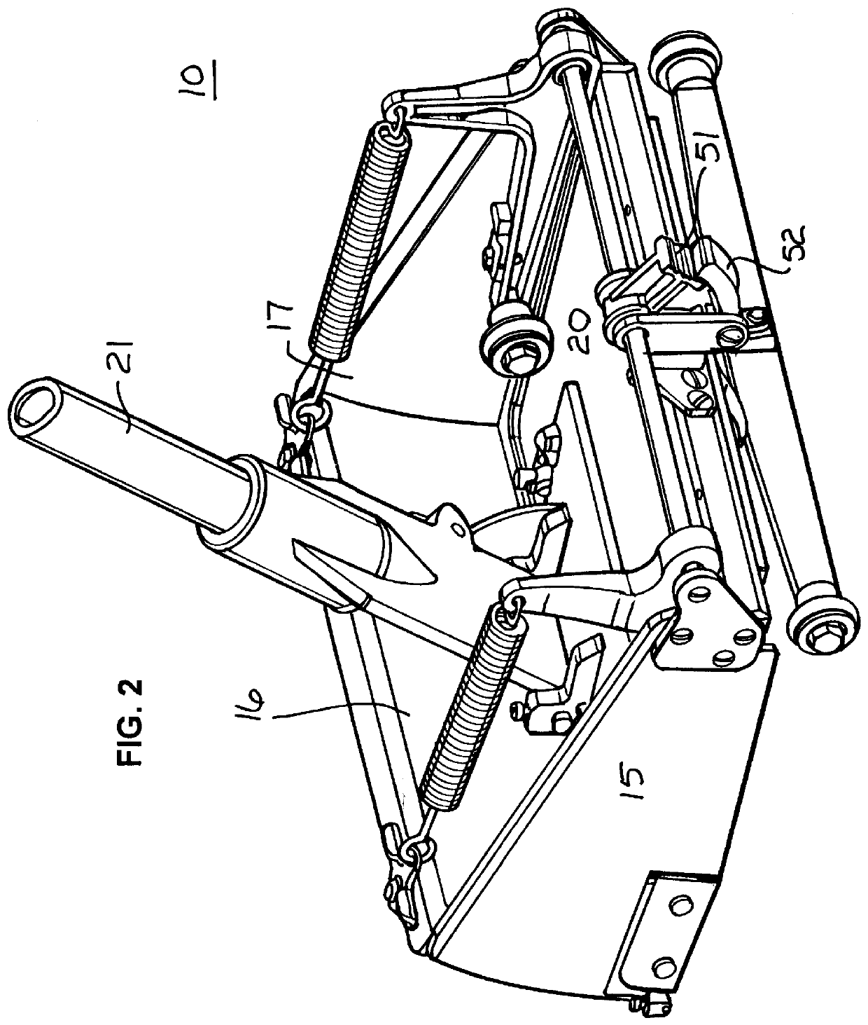
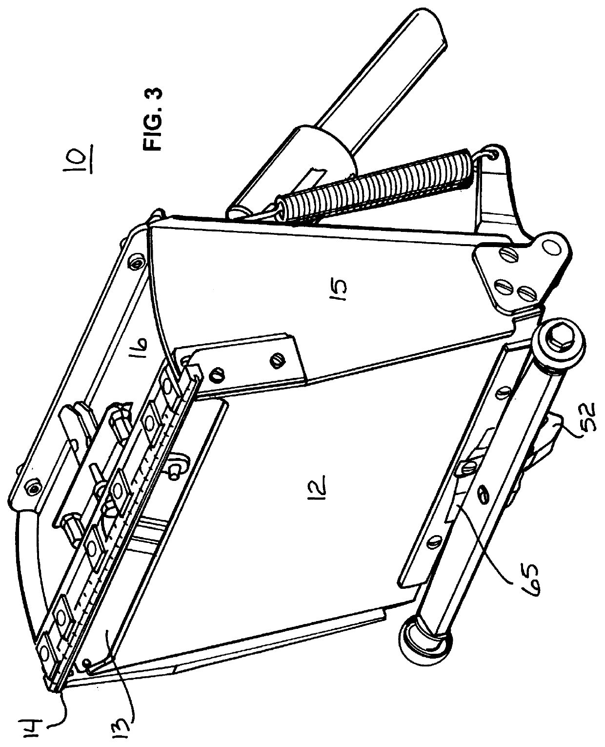
Turning now to the drawings in which like reference characters indicate corresponding elements throughout the several views, attention is first directed to FIG. 1 which illustrates a mud box 10 in accordance with the present invention. Mud box 10, which refers to the entire assembly, includes a box 11 with a bottom surface 12 (see FIG. 3) having an outlet orifice 13 through which joint compound or the like is extruded or ejected from box 11 under pressure. The extruded joint compound is then spread and smoothed by a squeegee or blade-like projection 14 on the underside of box 11, as mud box 10 is moved along a joint or wallboard surface. Box 11 further includes a left side 15, a front side or end 16, and a right side 17 (see FIG. 4). In addition to box 11, mud box 10 includes a cover 20 pivotally attached along the rear edge of box 11, and a handle 21 attached to cover 20 for positioning mud box 10 on a surface and applying extruding pressure to cover 20 for ejecting material throug...


PUM

PropertyMeasurementUnit
extruding pressureaaaaaaaaaa
tensionaaaaaaaaaa
angleaaaaaaaaaa

Abstract

A mud box includes a bottom surface with an outlet orifice, sides, a cover pivotally attached along one edge, and a handle attached to the cover for positioning the box on a surface and applying extruding pressure to the cover for ejecting material through the orifice. A spring assembly is attached to the box and connected to apply extruding pressure to the cover. A primary lock is coupled to the spring assembly and the box, the primary lock has a locked position in which the spring assembly is prevented from applying extruding pressure to the cover and an unlocked position in which the spring assembly applies extruding pressure to the cover. The primary lock is activated by a wheel assembly which moves it into the locked position when the box and wheel assembly are disengaged from a surface and which moves it into the unlocked position when the wheel assembly and box are engaged with a surface.

Description

FIELD OF THE INVENTIONThis invention relates to mud boxes for drywall joint compound application.More particularly, the present invention relates to mud boxes which automatically extrude or expel joint compound.BACKGROUND OF THE INVENTIONBoxes which are filled with joint compound for application to drywall joints and the like, hereinafter referred to as a "mud box", are well known in the art. Generally the mud box is constructed with an orifice in the bottom surface which operates as an outlet through which the joint compound is extruded or expelled. A cover on the mud box can be opened to allow the mud box to be filled with joint compound and when closed has springs attached to bias it toward the opened position. A handle affixed to the cover allows an operator to apply inward pressure on the cover to force the joint compound through the outlet slot and onto a joint or the like. The extruded joint compound is then spread and smoothed by a blade-like projection on the underside of t...

Claims


Application Information

Patent Timeline
Patent Type & Authority Patents(United States)
IPC IPC(8): B05C17/005E04F21/08E04F21/02
CPCB05C17/005E04F21/1652E04F21/165E04F21/06
Inventor POOL, DAN B.EDWARDS, TOBYKREITZER, DAVID F.
Owner EQUITY EARNINGS
Why Eureka
Try Eureka