Cam mechanism

a technology of cam mechanism and cam body, which is applied in the direction of couplings, manufacturing tools, gearing, etc., can solve the problems of the entire cam mechanism being made to a larger size than is desirable, and prolong the service life of the cam mechanism

Inactive Publication Date: 2001-02-13
SANKYO SEISAKUSHO
View PDF5 Cites 30 Cited by
  • Summary
  • Abstract
  • Description
  • Claims
  • Application Information

AI Technical Summary

Problems solved by technology

The result is that the periphery of turret 1 is made to relatively large dimensions which, in turn, results in the problem of the entire cam mechanism being made to a larger size than is de...

Method used


Image

  • Cam mechanism
  • Cam mechanism
  • Cam mechanism

Examples


Embodiment Construction

The preferred embodiments of the invention are directed to the invention as being applied as a tool changing mechanism for a metal processing machine.

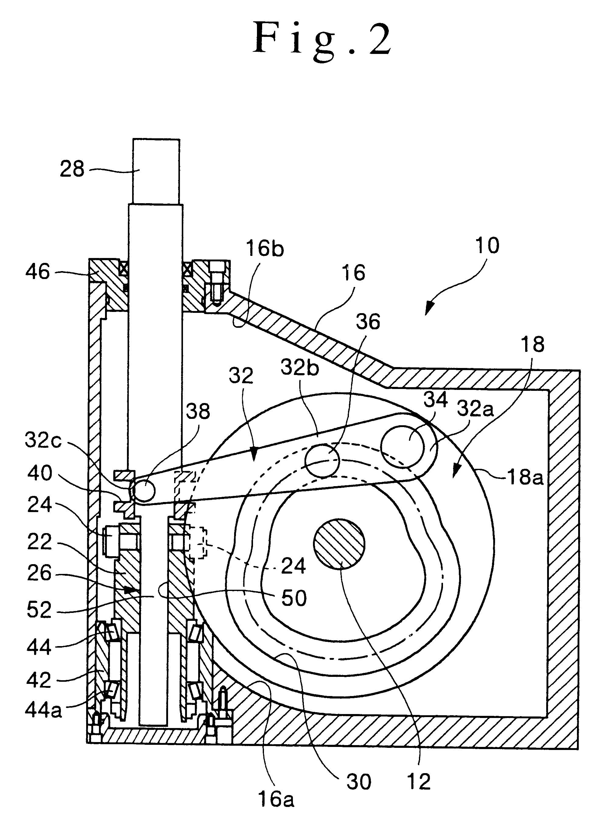
Rotational torque applied to input shaft 12 allows cam driven tool change mechanism 10, as shown in FIGS. 2 and 3, to provide the compound movement needed for a tool change cycle. Input shaft 12 is rotatably supported within housing 16 by means of roller bearings 14 and 14a, and is formed as a single integral structure together with roller gear cam 18.

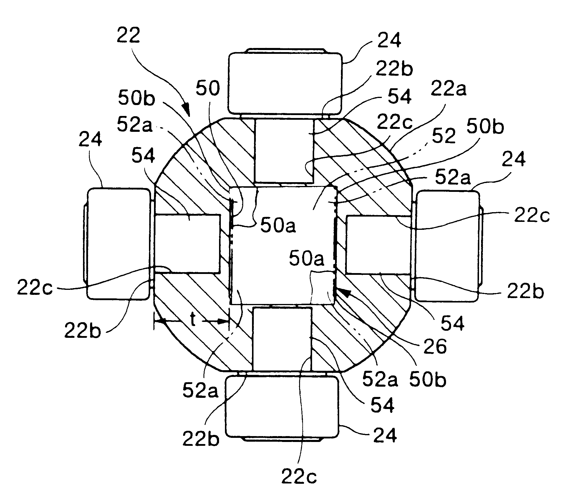
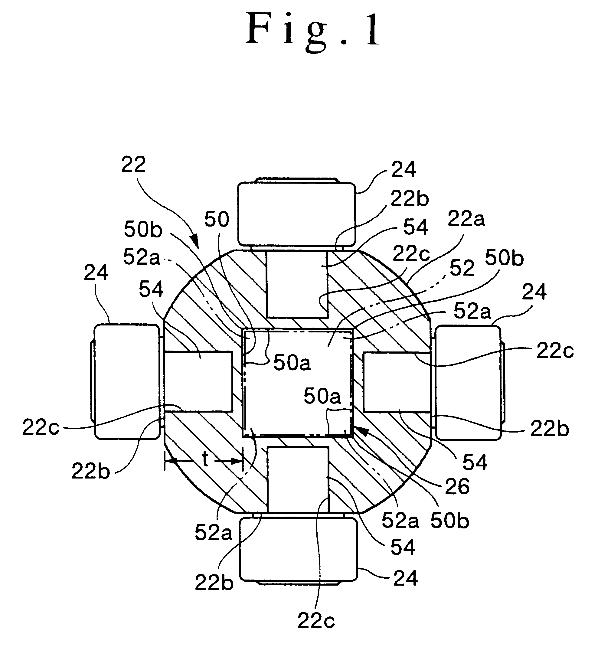
As shown in FIG. 6, geometrically curved tapered ribs 20 are formed on the periphery of roller gear cam 18, these tapered ribs 20 being disposed so as to mesh with cam followers 24 on the periphery of turret 22. The rotational movement of roller gear cam 18 and the placement of tapered ribs 20 on the cam's periphery imparts an oscillating rotational movement to turret 22 through cam followers 24, thus also imparting an oscillating rotational movement to output shaft 28 which is installed ...


PUM


Abstract

A cam powered mechanism which uses two cam forms, a swing arm, and turret to drive an output shaft with a compound radial and axial movement. An arrangement in which a cam follower is positioned opposite each planar surface of the rectangular spline connecting the turret and output shaft acts to increase turret strength and reduces the size of the mechanism.

Description

1. Field of the InventionThe invention relates to a cam driven mechanism in which the rotating torque applied to a roller gear cam is converted to the oscillating rotational movement of a turret and an output shaft by means of a cam follower.2. Description of the Related ArtThe type of cam mechanism mentioned above, which has been proposed by Japanese utility model publication 7-52444 (Int.Cl.F16H 37 / 16), operates by means wherein the rotating movement input to a cam mechanism is converted into a oscillating rotational movement of an output shaft on the radial axis, and also a reciprocating movement of the output shaft in the axial direction. This type of mechanism is commonly applied to the tool changing mechanisms of metal processing machines with the purpose of obtaining a fast and precise tool change indexing action.The aforesaid cam mechanism incorporates a roller gear cam fixedly attached to the input shaft, tapered ribs formed on the cam's periphery, and a cam channel formed ...

Claims


Application Information

Patent Timeline
IPC IPC(8): B23Q16/06B23Q3/155B23Q16/00B23Q5/34B23Q5/22F16H27/04F16H27/00F16H37/16F16H37/00F16D1/06F16H25/08F16H25/16
CPCB23Q3/1554B23Q5/341B23Q16/001F16H27/045F16H37/16B23Q16/065Y10T74/1828Y10T74/18528B23Q2003/155418B23Q2003/155428B23Q2003/155439
Inventor KATO, HEIZABURO
Owner SANKYO SEISAKUSHO
Why Eureka
Try Eureka