Method and apparatus for aligning stereo images

a stereo image and stereo image technology, applied in the field of stereo image alignment methods and equipment, can solve the problems of large viewer discomfort, large optical elements, and increased discomfor

Inactive Publication Date: 2001-02-20
VISTA MEDICAL TECH +1
View PDF10 Cites 199 Cited by
  • Summary
  • Abstract
  • Description
  • Claims
  • Application Information

AI Technical Summary

Benefits of technology

Still another object is to provide a method and apparatus for correcting stereo image misalignment problems which involves automatically capturing left and right electronic images (video image data), digitizing those images, processing the digitized images to achieve alignment, and processing the aligned digitized images to generate signals for driving a stereo display device.

Problems solved by technology

However, only a small degree of misalignment, in the form of differences in image size, vertical position and rotation, will cause viewer discomfort, and such discomfort increases as a function of the degree of misalignment.
Consequently prolonged viewing of misaligned stereo images, such as occurs in cardiac surgery or pneurosurgery operations, can produce a high degree of viewer discomfort.
However, in the case of a stereo endoscope the size limitation on the insertion portion of the endoscope results in the optical elements being quite small, making it difficult to mechanically adjust components to correct for misalignment errors.
Mechanical methods and means for correcting for misalignment errors of the type described are expensive and are not fully satisfactory for a number of reasons.
The electronic method embodied in the system of FIG. 3 of said patent is not explained or illustrated in specific detail but appears to have certain limitations.

Method used


Image

  • Method and apparatus for aligning stereo images
  • Method and apparatus for aligning stereo images
  • Method and apparatus for aligning stereo images

Examples


Embodiment Construction

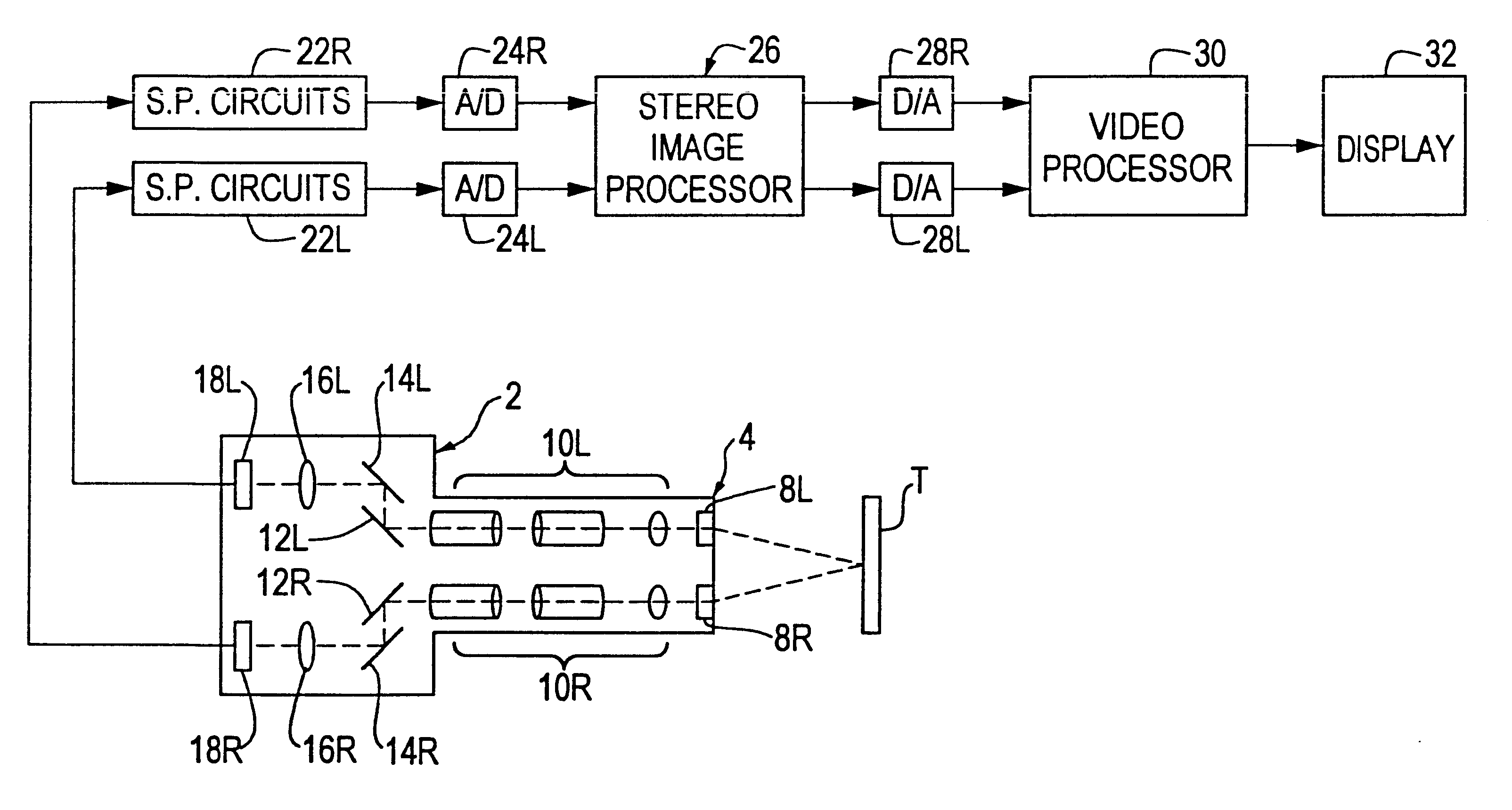
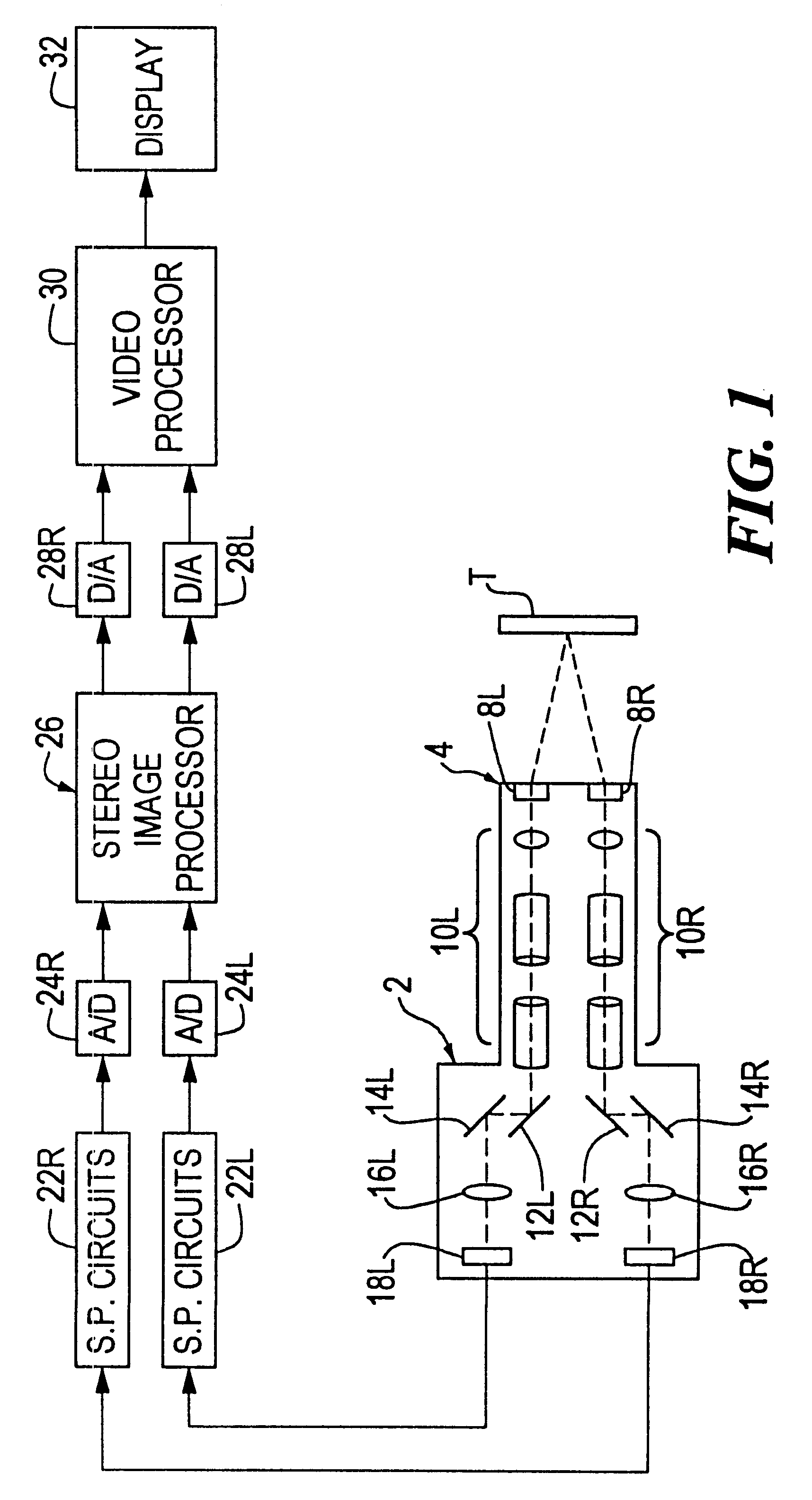
FIG. 1 illustrates diagrammatically a preferred form of image alignment measuring and adjusting system embodying the invention in combination with an electronic stereo endoscope. The latter comprises a housing 2 having a tubular insertion portion or barrel 4 containing two objective lenses 8R and 8L and two sets of relay lenses 10R, 10L. The housing also contains two pairs of 45.degree. mirrors 12R, 12L and 14R, 14L, and a pair of focusing lenses 16R, 16L. The foregoing optical components form two observation optical systems or channels, one right ("R") and the other left ("L"). The endoscope also contains a stereo video camera comprising two electronic imaging devices 18R and 18L, e.g., two CCD's, positioned to pick up left and right images with parallax between them that are focused by lenses 16R, 16L. Alternatively and preferably, each imaging device may be an RBG imaging device (not shown) that comprises a color resolution prism, an R-imaging CCD, a G-imaging CCD, and a B imagin...


PUM


Abstract

A method and apparatus are provided for correcting for optical misalignment of the dual (left and right) images produced by a stereo electronic endoscope, or of the corresponding dual images produced by coupling electronic imaging devices to each of two monocular teaching ports of a stereo optical endoscope. The stereo image alignment technique comprises electronically capturing the video image data of the dual images, and subsequently processing that data electronically to correct for optical alignment errors. The method involves digitizing the electronic data and digitally performing the equivalent of vertical image shift, and / or image size change, and / or image rotation as required to correct for any visual image misalignment.

Description

This invention relates to a method and apparatus for aligning left and right images generated by an electronic stereo camera and more particularly to stereo endoscopes and operating microscopes.A three-dimensional ("3D") vision endoscope or microscope, hereinafter referred to as a "stereo" endoscope or microscope, comprises a stereoscopic optical system for forming a 3D image of an object. The stereoscopic optical system comprises objective lens means arranged to pick up two slightly different images of a object that approximate the two views (left and right) provided by human binocular vision. The difference between the two views is known as parallax. By properly aligning and presenting the two optical target images to human binocular vision, a three-dimensional sense of the target is presented to the viewer.In the case of a conventional (non-electronic) optical endoscope or microscope the two optical target images picked up by the objective lens means are passed to a viewing syste...

Claims


Application Information

Patent Timeline
Patent Type & Authority Patents(United States)
IPC IPC(8): A61B1/00G02B23/24H04N13/00H04N13/239
CPCA61B1/00193G02B23/2415H04N13/0018H04N13/0051H04N13/0055H04N13/0239H04N13/0246H04N13/0296H04N13/0257H04N13/0434H04N13/0438H04N13/044H04N13/337H04N13/341H04N13/167H04N13/344H04N13/189H04N13/246H04N13/122H04N13/257H04N13/296H04N13/239
Inventor HORI, KOICHIROTHALER, HERBERT A.
Owner VISTA MEDICAL TECH
Why Eureka
Try Eureka