
Shift select lever device for manually-shiftable automatic transmission

a technology of automatic transmission and shift select lever, which is applied in the direction of mechanical control devices, manual control with single controlling member, instruments, etc., can solve the problems of manual valve in the hydraulic control circuit, manual valve inoperative, and heavy swivel operation of the shift lever for manual up- or down shifts

Inactive Publication Date: 2001-02-27
MAZDA MOTOR CORP +1
View PDF12 Cites 37 Cited by
  • Summary
  • Abstract
  • Description
  • Claims
  • Application Information

AI Technical Summary

Benefits of technology

The shifting arrangement may further include a restraint member secured to the base member. In the shifting arrangement, the control member is supported for slide movement in the second direction relatively to the shift lever, and the restraint member restrains slide movement of the control member in the second direction directed toward the manual gear shift selecting position so as to force the control member relatively to the shift lever when the shift lever is swiveled in the second direction from any one of the positions other than the automatic gear shift selecting position and the manual gear shift selecting position, thereby holding the control member in the connecting position and allowing the control member to move in the second direction following swivel movement of the shift lever when the shift lever is swiveled in the second direction between the automatic gear shift selecting position and the manual gear shift selecting position so as thereby to move the control member between the connecting position and the disconnecting position.
With the shifting arrangement of the invention of the type having the shift lever operative to swivel in the first direction for selecting a plurality of the automatic driving positions including the automatic gear shift selecting position arranged in the first direction and to swivel in the second direction for selecting the manual gear shift selecting position for manually shifting the automatic transmission one gear step-by-step, the control member is kept in the connecting position in which it connects the transfer of swivel movement of the shift lever to the manual valve while the shift lever is in the automatic driving positions, so as to shift the manual valve following the swivel movement of the shift lever in the first direction. When the shift lever is swiveled in the second direction to the manual gear shift selecting position from the automatic gear shift selecting position, the control member is moved into the disconnecting position in which it disconnects the transfer of swivel movement of the shift lever to the valve, the manual valve is not shifted even when the shift lever is swiveled in the first direction to shift the automatic transmission one gear up or down. This prevents the hydraulic control circuit from changing an oil distribution pattern for the forward gears to an oil distribution pattern for, for example, the neutral range and prevents aggravation of swivel operation of the shift lever. While the shift lever remains in the automatic driving positions, swivel movement of the shift lever in the second direction is never accompanied by slide movement of the control member from the connecting position to disconnecting position, which is desirable for avoiding bending and / or damages of the control member.
Because the control member is supported for slide movement in the second direction relatively to the shift lever, it is easy to operationally couple the control member and the shift lever together and to uncoupled them from each other. In consequence, the control member is independent from swivel movement in the second direction of the shift lever while the shift lever is out of the automatic gear shift selecting position and the manual gear shift selecting position, and moves following swivel movement in the second direction of the shift lever while the shift lever is in the automatic gear shift selecting position and the manual gear shift selecting position. The control member is urged toward the manual gear shift selecting position from the automatic gear shift selecting position by the biasing means, and the shift lever is prevented from forcing the control member toward the manual gear shift selecting position from the automatic gear shift selecting position. That is, while the control member slides in the second direction following swivel movement of the shift lever, it stays in the connecting position while remaining situated in the connecting position even though the shift lever swivels. The control member operationally couples the second swivel bracket means to the first swivel bracket means with the shifting cable fixedly connected thereto while it is in the connecting position and uncouples the former from the later while it is in the disconnecting position. Accordingly, operational connection and disconnection between the shift lever and the manual valve are reliably achieved.
In the case where the shift arrangement includes the first and second swivel bracket means for supporting the shift lever for swivel movement in both first and second directions, because the control member is supported at a plurality of positions in the second direction on the second swivel bracket means, the control member is prevented from bending due to a stress on a swivel axis of the shift lever when it hits the first swivel bracket means. The control member is adapted to be brought into engagement with the second swivel bracket as a result of slide movement, which provides a simple support structure for supporting the control member for slide movement on the second swivel bracket means.

Problems solved by technology

In the case where the automatic transmission equipped with the manual gear shifting feature is provided parallel shifting channels for range and gear selection, respectively, swivel movement of the shift lever is made in the same direction in the gear shifting channel as in the range shifting channel, so that the manual valve is moved through the shifting cable even during manual gear shifting, which leads not only to heavy swivel operation of the shift lever for a manual up- or down-shift, and hence aggravation of a feeling of operation of the shift lever but to an apprehension of a deviation from a proper hydraulic pressure line for the preselected range due to movement of the manual valve.
An immanent problem in the automatic transmission described above in which connection and disconnection of transfer of movement of shift lever to the shifting cable is caused directly by movement of the shift lever between the D and M positions is that, even while the shift lever remains in the range shifting channel to select positions other than D and M positions, if the shift lever receives load in the transverse direction as strong as it is forced in the same direction, the shift lever is operationally disconnected from the shifting cable with a result of making the manual valve in the hydraulic control circuit inoperative.

Method used


Image

  • Shift select lever device for manually-shiftable automatic transmission
  • Shift select lever device for manually-shiftable automatic transmission
  • Shift select lever device for manually-shiftable automatic transmission

Examples


Embodiment Construction

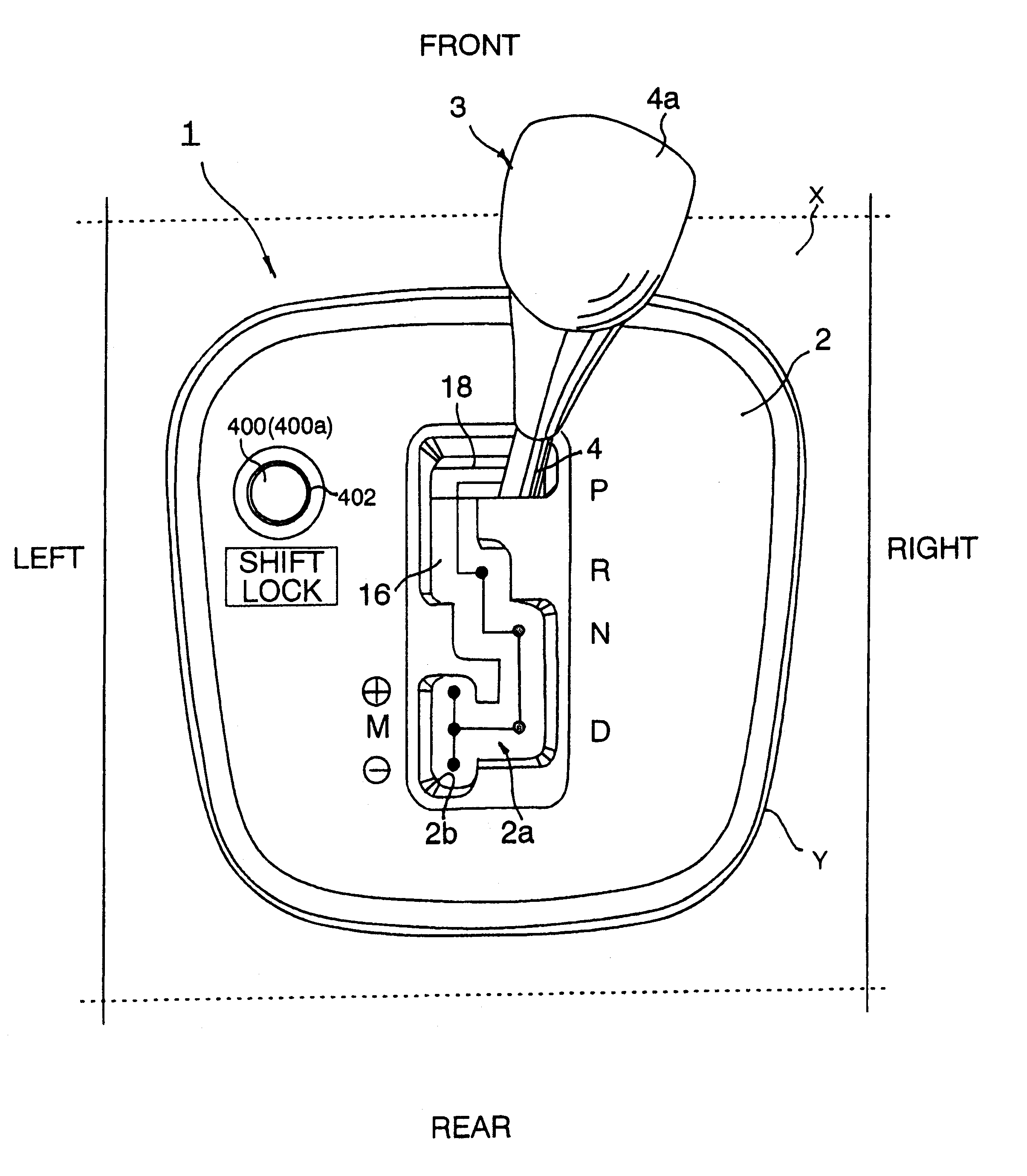
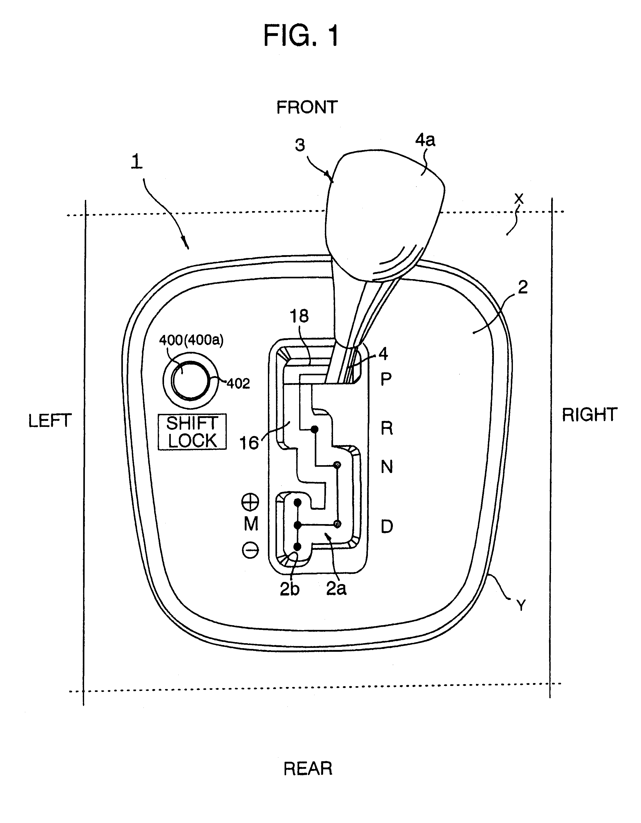
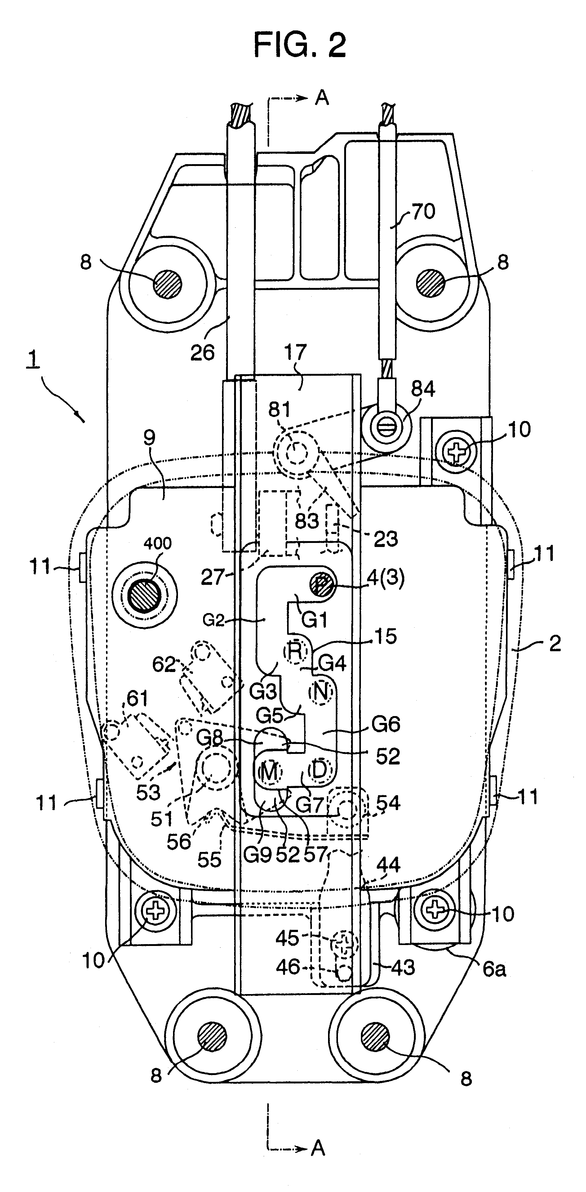
Referring to the drawings in detail, particularly to FIGS. 1 through 4 which show a shift arrangement 1 with a manual gear shift feature in accordance with an embodiment of the invention, the shift arrangement 1 is installed in a console X between separate seats (not shown) and has a cover panel 2 fitted into an opening Y of the console X. The cover panel 2 is formed with a shifting channel opening 2a extending in a generally lengthwise direction (which refers to the lengthwise direction of the vehicle from the front to the back) which is in conformity in shape with a shifting channel opening 15 (which will be described in detail later) formed in the upper panel 9. The shifting channel opening 2a has four automatic driving positions for positioning a shift or selector lever 3 to select available ranges, namely a parking (P) range, a reverse (R) range, a neutral (N) range and a drive (D) range. As shown in FIG. 4 in detail, the shift lever 3 comprises a lower plastic base member 5 (w...


PUM


Abstract

A shifting arrangement for an automatic transmission with manual gear shift feature has a control member which is operative to connect and disconnect operational linkage between a shift lever and a shift cable connected to a manual valve in a hydraulic control circuit. The control member is supported to slide relatively to the shift lever while the shift lever is operated between driving positions including an automatic gear shift selecting position so as that the shift lever remains operationally connected to the shift cable and is coupled to the shift lever when the shift lever is moved in the transverse direction from the automatic gear shift selecting position to a manual gear shift selecting position so as to operationally disconnect the shift lever from the shift cable. The shift lever is movable relative to the control member in the transverse direction when the control member is connected to the shift cable.

Description

1. Field of the InventionThis invention relates to a shifting arrangement for an automatic transmission of a motor vehicle, and more particularly, to an automatic transmission shifting arrangement which has a cable connecting a shift lever and a manual valve in a hydraulic control circuit to shirt the manual valve according to ranges selected by the driver through the shift lever.2. Description of Related ArtIn recent years, automatic transmissions of a motor vehicle of the type which permits a manual choice of gears in addition to automatic gear selection have been put into practical use. Such an automatic transmission automatically selects gears according to driving conditions in the automatic gear selection range and is manually shifted to intended gears selected by the driver through a shift lever. One of the automatic transmissions of this kind is known from, for example, Japanese Patent Application, laid-open to the public as Japanese Unexamined Patent Application No.7-280072....

Claims


Application Information

Patent Timeline
IPC IPC(8): F16H59/02F16H59/10B60K20/02F16H59/08
CPCF16H59/0204F16H59/10Y10T74/20049F16H2061/223Y10T74/20067F16H2059/0239
Inventor MIYOSHI, KEISUKEHIASA, FUMIHIKO
Owner MAZDA MOTOR CORP
Learn More